Electrostatics
All materials are made up of tiny particles of matter called atoms. Atoms are thought to be made up of smaller particles, some of which are electrically charged. A model of the atom is shown in the following figure
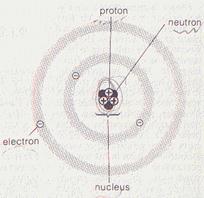
At the centre of each atom is a nucleus made up of particles called protons and neutrons. Surrounding this nucleus are very much lighter particles called electrons. Electrons have a negative (-) charge; protons have an equal positive (+) charge; neutrons have no charge.
Normally, atoms have equal numbers of electrons and protons, so the total amounts of negative and positive charge within a material are the same. The overall or net charge on the material is zero.
If a body gains some extra electrons it becomes negatively charged, if it loses some electrons it becomes positively charged. However, when two materials are rubbed together, electrons may be transferred from one to another. This upsets the balance between the opposite charges within each material, so that each is left with a net negative or positive charge.
Charging
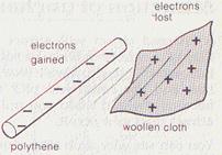
A. Charging by Rubbing is due to the transfer of some negative electrons from one material to another
· Polythene becomes negatively charged when it is rubbed with a dry woollen cloth.
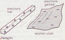
· Perspex/acetate becomes positively charged when it is rubbed with a dry woollen cloth.
B. Charging by Contact ..When a charged body touches an uncharged object, the two bodies will share the charge. Both will carry a part of the same charge.
Properties of a charged body
1. A charged body attracts light objects like dust, a small pith ball, small pieces of paper, etc
2. "Like charges repel ; unlike charges attract".
If a charged polythene rod is brought near a charged Perspex rod as in the following figure, it will attract it. On the other hand, a charged polythene rod will push away or repel another charged polythene rod
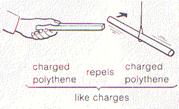
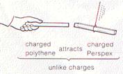
When rubbed with a dry, woollen cloth, a polythene rod becomes negatively charged, and a Perspex rod becomes positively charged.
The force of attraction or repulsion increases as the charges on the bodies increase, and the force decreases as the distance between the charges increases.
Note that rubbing materials together doesn't make charge; it simply separates negative arid positive charges which already exist within the materials.
Conductors and insulators
When rubbed, some objects lose charge almost as soon as they gain it. This happens because electrons flow through the object or surrounding materials until the balance of negative and positive charge is restored.
Materials which allow electrons to flow through them are called conductors. Materials which do not conduct charge are called insulators. Therefore materials may be classified into conductors and insulators.
A conductor material is that which allows the electric current to flow through it. Conductors are essentially metals, they contain free electrons which move freely in the conductor and can transfer the electric charge. These free electrons also make metals very good conductors of heat
Most non-metals conduct charge poorly or not at all, though carbon is an important. exception.
Insulators do not allow the current to flow through them, their electrons are tightly bound to their atoms and cannot move freely. These electron can of course be disturbed if a material is rubbed. Because of-this, insulators are relatively easy to charge, by rubbing because any electrons which are transferred tend to stay where they are. Examples: glass, rubber, sulphur, amber, etc
An insulator should be perfectly dry , moisture on an insulator can conduct electric charge and ruin the insulation.
A silk or nylon thread is used to hang a charged body because the thread acts as an insulator .
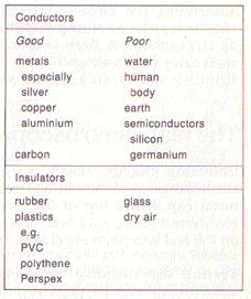
The following table shows some poor conductors, good conductors, and insulators.
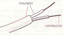 When you switch on a light, the
'electricity' passing through the cable is actually a flow of electrons.
The cable has copper conducting wires through its centre as shown in the
following figure. These are enclosed in an insulating material usually the
plastic PVC.
When you switch on a light, the
'electricity' passing through the cable is actually a flow of electrons.
The cable has copper conducting wires through its centre as shown in the
following figure. These are enclosed in an insulating material usually the
plastic PVC.
c. Electrostatic Induction
 It occurs due to the movement of free
electrons of a conductor from one side to the other under the effect of an
outside charge. An opposite charge is always formed towards the charging
body. Notice that no net charged is produced in the conductor; when the
charging body is removed, the conductor becomes uncharged again.
It occurs due to the movement of free
electrons of a conductor from one side to the other under the effect of an
outside charge. An opposite charge is always formed towards the charging
body. Notice that no net charged is produced in the conductor; when the
charging body is removed, the conductor becomes uncharged again.
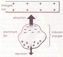
This is explains why charged body attracts uncharged body. You can see why such attractions occur by considering the effect of a charged Perspex rod on a small piece of aluminium foil placed just underneath it as shown in the figure. Free electrons in the aluminium are pulled towards the positively charged rod, the top end of the foil becoming negatively charged while the bottom end is left with a net positive charge. The charged rod; therefore attract the top end of the foil and repels the bottom end. As the top end is closer to the rod, the force of attraction is the stronger of the two forces and the foil is pulled towards the rod as a result.
Sometimes the force of attraction between charges on different objects may be so strong that the air separating them ceases to act as an insulator. A flash is seen, as moving electrons collide with molecules in the air and cause them to give out light as sparks on a smaller scale.
Producing of an opposite charge by induction
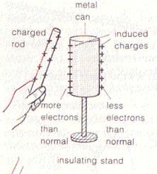
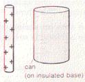
The following figure shows how a charged rod can be used to give a nearby conductor a charge of the opposite type. The process is called charging by induction. The rod in this case is made of Perspex and is carrying a positive charge. The conductor is a metal can and it is mounted on an insulating stand. The following are the steps:
1. Bring the charged rod near the conductor. ( conductor is polarized but it is still neutral)
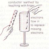
2. Connect the conductor to earth by touching it by a finger ( at any place ), this removes the similar charge at the far end
3. Disconnect the earthing (by removing the finger).
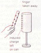
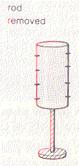
4. Finally remove the charging rod, the conductor is now charged with an "opposite" charge.
Quantity of Charge Q, is the amount of electric charge carried by the extra electrons ( or extra positive charges) on the charged body. It is given by:
Q = ne
Where, n is the number of extra electrons and e is the charge of each electron. The unit of the electric charge is the "Coulomb", C
The leaf electroscope
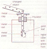 Detecting charge Small
charges can be detected using a leaf electroscope as shown in the following
figure. If a charged object touches the metal cap at the top of the
electroscope, some of 1he charge is transferred to the gold leaf and metal
plate at the bottom. Charges on the leaf and plate repel each other and
the leaf rises as a result.
Detecting charge Small
charges can be detected using a leaf electroscope as shown in the following
figure. If a charged object touches the metal cap at the top of the
electroscope, some of 1he charge is transferred to the gold leaf and metal
plate at the bottom. Charges on the leaf and plate repel each other and
the leaf rises as a result.
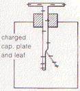 Testing for
negative or positive charge. Once
charged, an electroscope can be used to find out whether the charge on an
object is positive or negative. The following figure shows an
electroscope which has been given a negative charge; cap, plate and leaf all
contain more electrons than normal.
Testing for
negative or positive charge. Once
charged, an electroscope can be used to find out whether the charge on an
object is positive or negative. The following figure shows an
electroscope which has been given a negative charge; cap, plate and leaf all
contain more electrons than normal.
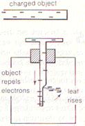
If a negatively charged object is brought towards the cap as in the figure, free electrons are pushed away from the cap and down into the leaf and plate. This increases the repulsion between the leaf and the plate, and the leaf rises even more.
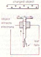
If a positively charged object is brought towards the cap as in figure, the reverse happens. Free electrons in the leaf and plate are attracted upwards towards the cap, and the leaf falls.
In general, the leaf of a charged electroscope rises if the object brought towards the cap carries the same type of charge, and falls if the object carries the opposite type of charge.
Questions
1. Name a material which, when rubbed with a dry cloth, becomes
a) negatively charged b) positively charged.
Explain in terms of electron transfer what happens in each case.
2. In an atom, what type of charge is carried by
a) protons b) neutrons c) electrons?
3. Why are metals such good conductors of charge? Name a non-metal which is also a good conductor.
4. Why doesn't a conductor become charged when it is held in the hand and rubbed with a cloth? How can a conductor be charged by rubbing?
5. A positively charged rod is brought towards the cap of an uncharged electroscope. Is there any effect on the leaf before the cap is touched? If so, explain why.
6. A leaf electroscope is given a negative charge. When a charged rod is brought towards the cap of the electroscope, the leaf rises even more. What type of charge is there on the rod? Give reasons for your answer.
7.
 In the figure below, a charged rod
has been brought close to an uncharged metal can. Copy the diagram and add any
induced charges you, would expect to find on the can. What would you need to do
in order to leave the can with negative charge?
In the figure below, a charged rod
has been brought close to an uncharged metal can. Copy the diagram and add any
induced charges you, would expect to find on the can. What would you need to do
in order to leave the can with negative charge?
Charged conductors
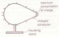
Experiments show that any charge gained by a conductor collects on its outside surface and is most concentrated where the surface is most highly curved.
Distribution of charge on a conductor
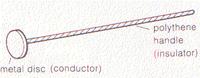 A proof plane as shown in the figure
is used for transferring small charge from a charged object to an electroscope.
A proof plane as shown in the figure
is used for transferring small charge from a charged object to an electroscope.
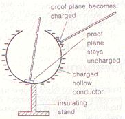 If a proof plane is touched against
the inside surface of a charged hollow conductor as in the figure, and then
placed against the cap of an electroscope, the leaf of the electroscope does
not rise. It will however rise if the proof plane is touched against any
part of the outside surface of the conductor, showing that: the
charge on a conductor collects only on its outside surface.
If a proof plane is touched against
the inside surface of a charged hollow conductor as in the figure, and then
placed against the cap of an electroscope, the leaf of the electroscope does
not rise. It will however rise if the proof plane is touched against any
part of the outside surface of the conductor, showing that: the
charge on a conductor collects only on its outside surface.
Further tests with a proof plane on different parts of the outside surface of a charged conductor as shown in figure show that in most cases the charge is not evenly distributed. The greatest deflection of the electroscope leaf occurs when the proof plane has been touched against the most highly cured part of the conductor surface. This shows that: the concentration of charge on a conductor is greatest where the surface is most sharply curved.
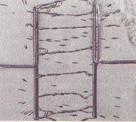
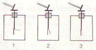
The lightning conductor
Tall buildings usually have a strip of copper called a lightning conductor attached to at least one side as shown in the following figure. One end of the strip is fixed to a metal plate buried in the ground; the other end is attached to a sharp spike or spikes which point upwards above the highest part of the building.
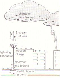
Thunderclouds carry electric charges. If, say, a negatively charged thundercloud passes over a building as in the above figure, a positive charge is induced on the roof, and the force of attraction between these opposite charges may be strong enough to produce a sudden flow of electrons from cloud to roof. In other words} the roof may be struck by lightning.
The lightning conductor reduces the risk to the building in two ways:
1. The flow of ions from the spikes lowers the induced charge on the roof and cancels out some of the charge on the cloud. This reduces the chances of lightning striking.
2. If lightning does strike, the lightning conductor provides a route for electrons to pass into the ground without damaging the building. The ground or earth has an almost infinite capacity for absorbing extra electrons.
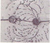
Electric fields
It is the region around the charged body in which an electric charge experience a force. Electric field is represented by the electric field lines. An electric field line shows the path which would be taken by a positive charge free to move in the field, with the arrow giving the direction of the force acting.
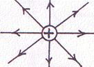
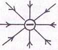
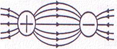
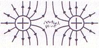
The lines of force are directed out of the positive charges and towards the negative charges. The density of lines is proportional to the strength of the field.
Questions
1.
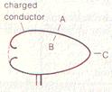 The figure shows a positively charged
hollow conductor. A proof plane is touched at point A and then placed in
contact with the cap of an electroscope. The experiment is repeated at
point B and then at point C. The lower diagrams show the possible effects
on the electroscope leaf. Which diagram corresponds ,
to each of the points of contact A, B, and C? What two properties of
charged conductors do these experiments demonstrate?
The figure shows a positively charged
hollow conductor. A proof plane is touched at point A and then placed in
contact with the cap of an electroscope. The experiment is repeated at
point B and then at point C. The lower diagrams show the possible effects
on the electroscope leaf. Which diagram corresponds ,
to each of the points of contact A, B, and C? What two properties of
charged conductors do these experiments demonstrate?
2. Give two functions of a lightning conductor .
3. Copy and complete the figure below to show the electric field, around a positively charged metal sphere.

Redraw the diagram to show the electric field around a negatively charged sphere. What would happen in each case to a positive charge placed at point X if the charge were free to move?
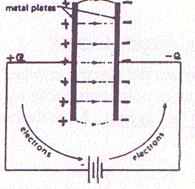 Capacitors :
A capacitor is used to store electric charges and electric energy. A parallel plate capacitor consists of two metal plates separated by an insulator when it is connected to a battery, the two plates are charged with equal and opposite charges. The voltage of the capacitor increases gradually until it becomes equal to the voltage of the charging battery.
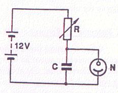
Flasher Neon Lamp by using a capacitr
The diagram shows an electric circuit to study the charging of capacitor C. The neon lamp N flashes whenever the p.d. across the capacitor C reaches 11 V. C is then discharged, the lamp goes out and the p.d. across C slowly increases once more and the whole process is repeated over and over again. When the resistance R is increased, the charging of C becomes slower and the lamp flashes less frequently.
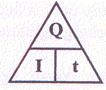
The Electric Current :
When the electric charge, Q , flows from the positive pole of a battery to the negative pole it produces a current.
The current, I, is defined as the charge flowing per unit time, i.e
![]()
Q = I.t
Q is measured in Coulombs and I in Amperes. The current flowing in a circuit is measured by an ammeter, connected in series in the circuit.
1 Ampere = 1 Coulomb / second.
Therefore the ampere may be defined as the value of the current in the circuit if a charge of one coulomb passes in one second.
Example:
If the current through a flood lamp is 5A, what charge passes in
a)10
seconds.
b) 5 minutes
Solution
a) Q = I.t = 5(10) = 50 coulombs
b) Q = I.t = 5(5.60) = 1500 coulombs
How current flow in the circuit or in conductors?.
In metal, each atom has one or more free electrons. These electrons are free to move. When a battery connected across the ends of such conductor, the free electrons drift slowly along it in a direction from the negative to the positive terminal of the battery. There is then a current of negative charges. This is equivalent to flow of positive charge from the positive terminal of the battery to the negative terminal through the conductor (conventional current).
It may be noted that current need a complete path (circuit) of conductor to flow. In the above figure the current flows from the positive terminal of the battery to the negative terminal through the lamp and the connecting wires.
Circuit diagrams.
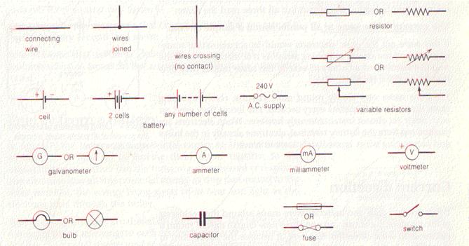 Wires of copper are used to connect
sources (batteries), elements (switches), and loads (lamps). If the wires
are covered with insulation, e.g. plastic, the ends are bared for connecting
up. Following are some of electrical symbols used in electric circuits.
Wires of copper are used to connect
sources (batteries), elements (switches), and loads (lamps). If the wires
are covered with insulation, e.g. plastic, the ends are bared for connecting
up. Following are some of electrical symbols used in electric circuits.
Measuring the current
The electric current is measured using Ammeter. The Ammeter is connected in series in the circuit as shown in the following experiment.
1. Connect the circuit as shown in the following figure ensuring that the + of the cell is connected to the + of the Ammeter and note the current
2. Connect the circuit as shown in the following figure. The cells are in series (+ of one to – of the other), are the lamps.
3. Recode the current
4. Measure the current at B, C and D by disconnecting the circuit at each point in turn and inserting the ammeter.
5. What did you notice?
6. Connect the circuit as shown in the following figure. The lamps are in parallel. Read the ammeter.
7. Measure the current at P, Q and R.
8. What is your conclusion
Potential Difference: P.D.
|
|
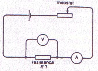
When a current flows in an electric circuit, the electric potential
energy at each point is different from that at other points. The
potential difference across a component, R , is the
energy which derives the current through the component. P.D.
is measured by a voltmeter connected in
parallel with R, and it is measured in "volts"
The above figure shows how to connect the ammeter and voltmeter to measure the voltage drop (potential difference) across the resistance and the current flow in this resistance.
Electromotive Force (EMF):
EMF of a battery is the total p.d. across its terminals, it equals the sum of all p.d' s across the components of the circuit.
The EMF of a battery is the energy needed to drive one coulomb of charge around the whole circuit.
Therefore the one volt may be defined as the value of the energy in joule needed to drive a charge of one coulomb around the whole circuit
EMF
= 
Example: A current of 4 A flows from a battery when a light bulb is connected across its terminal. The potential drop across the terminals is 12 V. Find
a) The quantity of charge leaves the battery in 5 second
b) The energy supplied by the battery produce the charge produced in part a
c) The quantity of charge leaves the battery every second
d) How much potential energy does each coulomb leave the battery posses
e) How long does the battery take to supply 60 joule of energy
Solution
a) Q = I.t = 4(5) = 20 C
b)
EMF =
12 = ![]()
Energy = 12(20) = 240 J
c) Q = I.t = 4(1) = 4 C
d) Energy = Q.(EMF) = 1(12) = 12 J
e) Energy = Q.(EMF) = (I).(t).(EMF)
t =![]() =1.25 s.
=1.25 s.
Comparison between Ammeter and Voltmeter
|
Ammeter |
Voltmeter |
|
· Measures the current in Amps · Connected in series in circuit · Has very low resistance (not affecting the voltage in the circuit) |
· Measures the p.d. in Volts · Connected in parallel with the component · Has very high resistance (not affecting the current in the circuit) |
Resistance "R"
Each component in a circuit (e.g. a wire, a lamp) has certain resistance to the flow of current. The resistance is measured in ohm (W).
Ohm's Law:
Experiments showed that: "The current passing through a resistor is directly proportional to the potential difference across its ends".

![]() i.e
i.e
OR
R = ![]() ,
OR I =
,
OR I =
![]()
Where R is a constant representing the resistance of the circuit component (may be a lamp or an apparatus).
The ohm may be defined as the resistance of a conductor in which the current is 1 ampere when a voltage across it is 1 volt.
Examples:
· A p.d. of 12 V is needed to make a current of 2 A flow through a wire of resistance 6 W
· A current of 4 A will flow if there is a p.d. of 20 V across a wire of resistance 5W
Resistors
Devices specially made to provide resistance are called resistors. Placed in simple circuit, they each reduce the current flow.
The Resistance of a Metal Wire, R ,
It is found that:
· R is directly proportional to the length of wire, l .
· R is inversely proportional to its cross-sectional area, a .
· R depends on the resistivity of the substance of the wire, r .
· R for a metal wire increases as the temperature rises (not directly proportional).
The first three factors are combined to get the formula :
![]()
The following figure summarizes the relationship between the resistances and the above factors.
Variable resistor
A variable resistance is made of a long coil of wire and a slider moving on a long thick bar and touching the wire as shown in the following figure
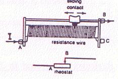
There are two ways of using such variable resistor. It may be used as rheostat for changing the current in the circuit. In this case, the current is usually connected to one end of the wire and leaves from the other end of the thick bar. By moving the slider away from the point at which the current enters the rheostat, the resistance increases, and vice versa. The following figure shows the use of variable resistance as rheostat.
The variable resistor may also used as potential divider. In this case, it is used for changing the p.d. applied to the device. The following figure shows the use of variable resistor as potential divider.
Measuring the resistance
The resistance of a conductor by measuring the current I through the resistance using ammeter when a p.d. V is applied across it using the R = V/I. This is called ammeter-voltmeter method.
· Setup the circuit as shown in the above figure.
· Record the reading of the current (I) and the voltage (V)
· Work out R for this reading
· Altering the reohstat changes both p.d. and I, record the reading, and workout R
· Repeat the above steps three times and take the average.
Note that the value of R may be obtained graphically by plotting the curve between V and I and taking the slope of the line.
Remark:
When measuring the resistance of a filament lamp, the results show that its resistance increases gradually as the current increases due to the increaase in of the filament's temprature.
Resistors connected in Series.
The rsistors (R1, R2 and R3) in the above figure are connected in series. It may be noticed that:
1. The current, I, passing in all the resistors is the same (the reading of (Al) equals the reading of (A2).
2. The p.d. across each resistor depends on the value of the resistor, thus V1, V2 & V3 have different values. But the sum of all p.d.'s must equal the total p.d. across the battery, or
Total potential drop across the battery = Sum of the potential drop across the resistors
V = V1 + V2 + V3
Note that V1 = IR1, V2= IR2, V3 = IR3, and V = IRt
Where Rt is the equivallent resistance (total resistance or effective resistance)
3. The equivallent resistance = Sum of all resistances
Rt = R1 + R2 + R3
Note that: the current in circuit may be reduced by inserting a seires resitance in the circuit.
Resistors connected in parallel.
The rsistors (R1, R2 and R3) in the above figure are connected in parallel. It may be noticed that:
1. The p.d across each resistor is equal to that of the battery.
2. The values of the currents I1, I2, and I3, are different and depends on the value of each resistanc, thus
I1 = ![]() ,
I2 =
,
I2 = ![]() ,
I3 =
,
I3 = ![]() ,
,
3. The total current, I, through the battery is distributed among the resistoor R1, R2, and R3. i.e.
I = I1 + I2 + I3, Thus
![]() =
=
![]() +
+
![]() +
+![]()
4. The equivallent resistance of the three resistance connected in parallel is given by
![]() =
=
![]() +
+
![]() +
+![]()
It may be noted that the equivllent rsisstane is smaller than any value of the resistance conneted in parallel
For simpler case of two resistors in parallel, the equivallent resistance is given by:
Rt = 
NOTE:
· When two equla resistances connected in parallel the combined resistance equal to half the value of one resitance
· When three equal resitances connected in parallel the combined resistance equal to one third the value of one resitance
· What is the combined resistance of a resiatance of 5 W connected in parallel to wire with zero W resistance?
Example :
A p.d. of 24 V from a battery to a network of resistors in the following figure
a) What is the combined resistance of the 6 W and 12 W rsistors?
b) What is the total circuit resistance?
c) What is current in the battery?
d) What is the current in the 8 W resistor
e) What is the voltage across the 6 W resistor
f) What is the voltage across the 12 W resistor
g) What is the current in the 6 W resistor
h) What is the current in the 12 W resistor
Solution
The combined parallel resistance Rp = 6*12/(6+12) = 4 W
The total resistance = 4+8 = 12 W
The current I = 24/12 = 2 A
The current in the 8 W resistor = I = 2 A.
The voltage across 6 W = Voltage across the 12 W = Voltage across 4 W
= 4(2) = 8 V
The current in the 6 W resistor = I1 = ![]() =
8/6 =1.33 A.
=
8/6 =1.33 A.
The current in the 12 W resistor = I2 = ![]() =
8/12 =0.67 A.
=
8/12 =0.67 A.
Or, I2 = I – I1 = 2 – 1.33 = 0.67 A.
Questions
1. What is the resistance of a lamp when a voltage of 12V across it causes a current of 4A?
2. Calculate the p.d. across a 10 W resistor carrying a current of 2A.
3. The p.d. across a 3 W resistor is 6V. What is the current flowing (in ampere)?
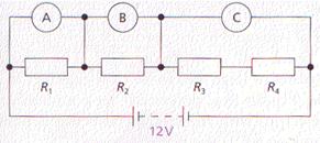
4. The resistors R1 R2 R3 and R4 in the following figure are all equal in value. What would you expect the voltmeters A, B and C to read, assuming that the connecting wires in the circuit have negligible resistance?
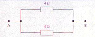
5. Calculate the effective resistance between A and B in the following figure
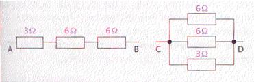
6. What is the effective resistance in the following figure between
a) A and B, b) C and D?
7. The following figure shows three resistors. Their combined resistance in ohms is
A) 1![]() B) 14
C) 1
B) 14
C) 1![]() D) 7
D) 7![]() E) 6
E) 6 ![]()
8. A student investigates how the current flowing through a filament lamp changes with the voltage across it. She is given a filament lamp and connecting wire. She decides to use a 1,5V power supply, a variable resistor, an ammeter, a voltmeter and a switch.
a) Complete the circuit diagram, started in with the following figure, to show how she should set up the circuit.
![]()
b) The student obtains the following results.
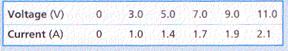
(i) Plot a graph of current against voltage.
(ii) Use your graph to find the current when the voltage is 10V.
(iii) Use your answer to (ii) to calculate the resistance of the lamp when the voltage is 10V.
c)(i) What happens to the resistance of the lamp as the current through it increases?
(ii) Explain your answer.
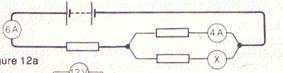
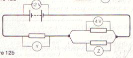
9.
In figures a and b what will be the
readings on the meters Xi Y and Z?
|
|
|
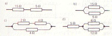
10. Calculate the combined resistance in each case of the resistors in figures a, b, c, and d.
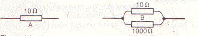
11. In the following figure, which resistor arrangement, A or B, has the lower combined resistance?
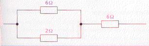
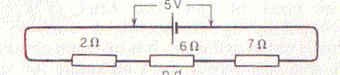
12. In the following figure, what is the p.d. across the 6 W resistor?
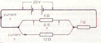
13. In the following figure, calculate
a) the current in the main circuit
b) the p .d across the 4 0 resistor
c) the currenl through the 120 resistor.
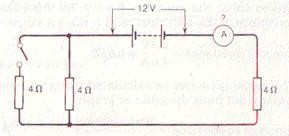
14. In the following figure, the switch is open. What will be the reading on the ammeter? What would the ammeter reading be if the switch were closed?
Practicle Preacautions
I. Connecting wires should be clean and should be tightened to make "good connection". Rusty, loose wires make "bad connections" which can increase the resistance and can produce jerky fluctuations in readings.
II. For ammeter and voltmeter, be careful to connect the positive side of instrument towards the positive of battery, and negative side towards the negative of battery .
III.Place the ammeter or voltmeter on a horizontal bench and tap its surface gently so as to allow its pointer to move freely before recording the reading.
* The eye should be perpendicular to the pointer to avoid the error due to parallax.
IV. When taking a reading from ammeter, voltmeter ( or oscilloscope) be careful about the calibration of the scale used.
* One should choose the range which gives the greatest deflection of pointer so as to get greater accuracy.
V. If
no unit is specified on the instrument, find a relation between the no. of , divisions on the instrument and the value of maximum
current. From this relation one can calculate the current for each
division.
Dr. Adel
A. El-samahy