Power Train
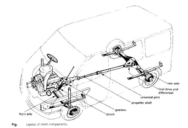
The Clutch
A clutch is a device for connecting or disconnecting two shafts. It may be a dog clutch, where the engagement is positive through projections on one member mating with corresponding indentions on the other, or a friction clutch, where the torque is transmitted through friction surfaces which allow a progressive engagement as they are brought together.
A friction cultch is necessary between the engine and gearbox to disengage and permits a smooth and gradual re-engagement of the drive. When engaged, the clutch must transmit the maximum engine torque without slipping, and when disengaged for gear changing it must not exert a drag on the idle member.
The internal combustion engine must revolve at a reasonable speed to develop sufficient torque to move the vehicle from rest and, when starting this engine torque must be smoothly and gradually conveyed to the gearbox without shock at the transmission.
The single-plate dry clutch:
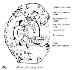 The driving members of the clutch consist of the
flywheel and the pressure plate both being of cast iron. The pressure plate is
caused to revolve with the flywheel by three or four sets of tempered-steel
straps arranged tangentially between the pressure plate and the cover, whilst
their flexibility in bending allows for the axial movement of the pressure
plate. Alternatively projections on the pressure plate engage and slide in
slots in the cover.
The driving members of the clutch consist of the
flywheel and the pressure plate both being of cast iron. The pressure plate is
caused to revolve with the flywheel by three or four sets of tempered-steel
straps arranged tangentially between the pressure plate and the cover, whilst
their flexibility in bending allows for the axial movement of the pressure
plate. Alternatively projections on the pressure plate engage and slide in
slots in the cover.
A series of springs located between the cover and the pressure plate force the latter towards the flywheel face, trapping the friction-lined driven plate or clutch disc between these two surfaces.
The clutch shaft supported in the gearbox by a journal bearing and in the flywheel by a spigot bearing is splinded to fit the hub of the clutch disc and transmits the torque from the driven disc to the gearbox.
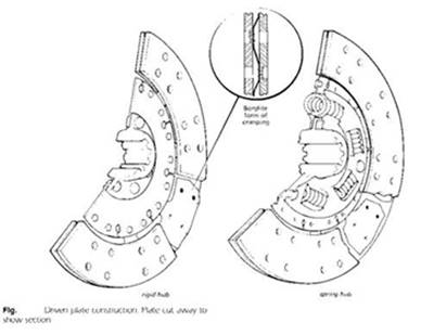
The driven plate may incorporate a spring-cushioning hub to reduce shock loading during engagement and absorb tensional vibrations. The hub springs can be arranged to have a progressive action by varying rates or end clearances, and some form of friction damping can be provided between the hub and the plate to absorb the tensional energy.
The riveted-on linings are of bounded asbestos and have a coefficient of friction on the cast-iron surfaces of 0.3-0.4. The spring-steel leaves carrying the linings may be arranged to slightly separate the two rings of material when free, so as to give a smooth action as they pressed together during engagement. Slotting the plate eliminates heat distortion.
|
|
|
|
The multi-plate clutch
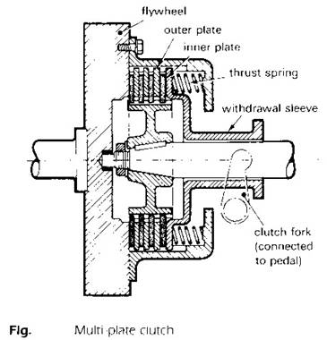 The torque transmitted by a plate-type clutch depends
on four factors, the number of friction surfaces (n), total spring thrust
(normal force) (Fn), Coefficient of friction (m),and the mean radius (rm). The formula to calculate the
torque capacity is
The torque transmitted by a plate-type clutch depends
on four factors, the number of friction surfaces (n), total spring thrust
(normal force) (Fn), Coefficient of friction (m),and the mean radius (rm). The formula to calculate the
torque capacity is
T = n m Fn rm
Where
Rm = (ro+ ri)/2
ro is the outer radius of the friction material,
ri is the inner radius of the friction material.
There are cases where the springs thrust, friction, or clutch radius must be restricted, so in theses cases the number of plates has to be increased to ensure that the maximum torque can be transmitted without slip. A clutch having more than one driven plate is called a multi-plate clutch.
This type of clutch was widely used on cars on the past but a modern use of a multi-plate type is in automatic gearboxes. This type of gearbox needs a number of clutches to hold the various gear elements, and since the clutch diameter in this application is limited, a multi-plate clutch is commonly used. The clutch may be either wet or dry. The clutch employed in the automatic gearbox is generally of the wet type, and is operated by a piston controlled by hydraulic pressure.
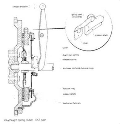
Diaphragm-spring clutch:
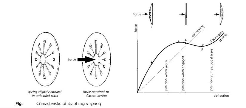
In the diaphragm-spring clutch the coil springs and the releases livers are replaced by a Belleville-type spring-steel ring slightly coned when free, flat when providing the clamping load, and coned in the reverse direction during withdrawal.
The diaphragm spring pivots on two fulcrum rings held by shouldered rivets to the clutch cover. Alternatively, the rings may be secured by integral tongues on the cover pressing, which are clenched over during manufacturing assembly. The outer rim of the diaphragm spring is retained in the pressure plate and its inward-pointing tapered fingers are acted upon by the release bearing.
The force produced by a diaphragm spring is not directly proportional to the deflection, i.e. it does not follow Hook’s law. Consequently clutch-pedal forces can be reduced whilst the clamping-spring pressure remains almost constant throughout the life of the linings. Other advantages of the diaphragm-spring clutch are a simplified construction, a more even circumferential clamping force, an independence of centrifugal force (unlike coil springs), and a more accurate balance.
Example:
An engine develop 146 N.m torque which is transmitted through a single plate clutch of mean diameter 250 mm. If the coefficient of friction between the surfaces is 0.3, calculate the minimum total clutch-spring force required to transmit this torque.
Let Fn be the minimum total spring force. This is the normal force between the surfaces. The friction force for the two sides of a single-plate clutch = 2 m Fn [N], hence
Tcl = 2 m Fn r [N.m]
Where: r = mean radius [m], then
Fn = Tcl /(2 m r ) [N]
= 146/ (2 x 0.3 x 0.125)
= 1946.7 [N]
The minimum total clutch-spring force required to transmit the torque without slip will be 1946.7 N.
The clutch torque actually designed with a higher value than the engine maximum torque.
Tcl = fd Te mas
Where:
Te max = maximum engine torque.
fd = design factor (safety factor) = 1.2- 1.6
the design factor is to accommodate for the; increase in engine torque, wear in the friction material (decrease in normal force), decrease in coefficient of friction.
Direct Shift Gearbox (DSG):
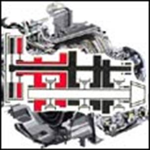
The (DSG) is a double clutch, which consists of two
wet plate-type clutches with hydraulically regulated contact pressure. One of
the two clutches engages the odd-numbered, the other the even-numbered gears.
This principle enables gear shifts to be made without interrupting the power
flow and keeps the shift times extremely short. While the first clutch is
transmitting the power, the second clutch is ready to engage the next gear,
which is preselected. When the driver makes the gear shift, the first clutch is
released and the second engages, so that the gear shift takes place in a
fraction of a second.
The driver can operate the DSG manually or allow changes to take place
automatically. In the automatic mode there is a choice between the
well-balanced, comfortable standard shift settings and a program with greater
sports emphasis. Manual shifts are made either at the gear lever
or at shift paddles behind the steering wheel.