Finding the Gearbox and Final Drive Ratios and Efficiencies
The internal combustion engine used in a modern vehicle will only operate over a limited effective speed range, e.g. 1500-5000 rev/min, and in this range will produce a comparatively low torque (turning effort). When the speed drops below the lower limit, or if the load is too great, the engine will stall and the vehicle will come to rest.
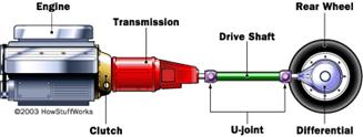
The transmission (gearbox) or transaxle is a vital link in the power train of any vehicle. The propose of the transmission or transaxle is to use gears of various sizes to give the engine a mechanical advantage over the driving wheels. Gears in the transmission or transaxle housing alter the torque and speed of this power input before passing it on to the other components in the power train. Without the mechanical advantage the gearing provides, an engine can generate only limited torque at low speeds. Without sufficient torque, moving a vehicle from a standing start would be impossible. The transmission or transaxle provides the gearing needed to reverse direction so the vehicle can be driven backward.
The necessity for a gearbox
Power from a petrol or diesel reciprocating engine transfers its power in the
form of torque and angular speed to the propelling wheels of the vehicle to
produce motion. The object of the gearbox is to enable the engine’s turning
effect and its rotational speed output to be adjusted by choosing a range of
under- and overdriving gear ratios so that the vehicle responds to the driver’s
requirements within the limits of the various road conditions.
Al low engine speed, a reciprocating-piston engine does not develop sufficient turning effort or torque to propel a vehicle forward from standstill. Even the greater torque produced at higher engine speed would be insufficient to accelerate the vehicle at a reasonable rate. The gearbox provides a way of varying the engine’s output torque and speed to match the vehicle’s speed and load.
* The high gear ratio means the lower is the reduction between the engine and the road wheels. Conversely the lower the gear ratio means the greater is the reduction between the engine and road wheels.
There will be power (energy) losses when using gear system to transmit the torque, which is due to many factors like, friction between gear teeth, the motion of lubricant in the gearbox,…
Output power = input power × η
Output power = input power – friction power
Using the above equation we can obtain the gearbox efficiency at each shift.
Terminology and defections:
Te = engine torque (N m)
Ne = engine speed (rpm)
ig = gearbox reduction ratio (1: ?.??? ) (ig1 = 1st
gear reduction ratio, ….)
ηg = gearbox reduction efficiency (0.00) (ηg1=1st
gear reduction efficiency, …)
if = final drive ratio 1: (?.???)
ηf = final drive efficiency (0.00)
it = total power train reduction ration (ig × if) (0.00)
ηt = total drive efficiency (ηg × ηf) (0.00)
n = number of gear teeth
rw = wheel radius (m)
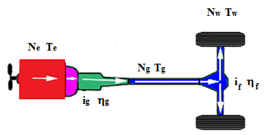
The gear ratio (ig) of a gear train is the ratio of the angular velocity of the input gear Ne (engine side) to the angular velocity of the output gear Ng (propeller shaft and differential side), also known as the speed ratio of the gear train. Hence, ig = Ne/Ng
The final drive ratio (if) of a differential unit of drive shaft is the ratio of the input angular velocity Ng (propeller shaft side) to the unit to the output velocity of the unit Nw (drive axle and drive wheels side). Hence, if = Ng/Nw
The total drive ratio (it) of a vehicle is the ratio between the engine angular velocity Ne to the drive axle and driving wheel angular velocity Nw. Hence, it = ig × if = (Ne/Ng) × (Ng/Nw) = Ne/Nw
Method of finding the gearbox ratios:
a) From the car manuals.
b) The
gear ratio can be calculated:
Directly from the number of teeth of the various gears that engage to form the
gear train. The torque ratio of the gear train, also known as its mechanical
advantage, is defined by the gear ratio.
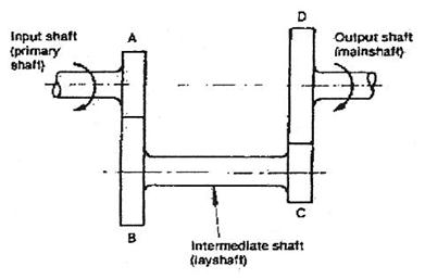
Finding the gearbox reduction ratios:
ig = (nD/nC) × (nB/nA) = (nD×nB) /(nC×nA) = (the multiplication of driven gears teeth numbers) divided by (the multiplication of driving gears teeth numbers), for the manual gear reduction shift gear combination.
Example: Gearbox reduction ratios ig
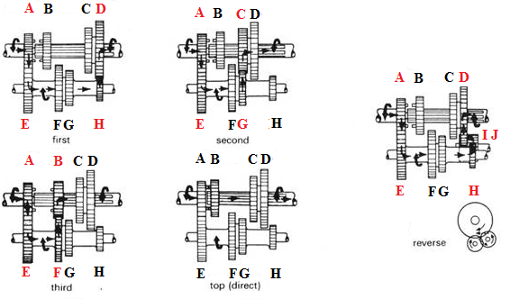
ig1
= (nD × nE) / (nH × nA), ig2
= (nC × nE) / (nG × nA), ig3
= (nB × nE) / (nF × nA),
i4 = Direct drive = 1.00, igR =
(nD × nJ × nE) / (nI × nH × nA(
Finding the final drive ratio:
By counting the number of teeth of crown and pinion gears.
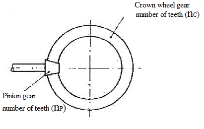
if = nC/nP
c) Obtaining the reduction rations and efficiencies by carry on experiments:
Method (I) (the units outside of the car):
(A) Finding the gearbox (gear ratios (ig..) and shifts efficiency (ηg...) Torque Balance:
The gearbox reduction ratios
can be found by experiment. Brief details are given below:
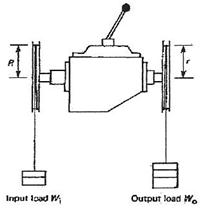
Fix a pulley on the input shaft and another one on the output shaft. Place a
chalk marks on the input and output pulley. Count the number of revolutions on
the input pulley needed to complete one revolution of output pulley. Repeat for
each gear ratio.
ig = revolutions of input pulley / one
revolution of output pulley
The shift efficiencies can be found by the following experiment:
Put a rope over each pulley and
a) Balance the input and output weights attached to the ropes (no
motion);
ηg = output torque / (input torque × ig)
= (wo × r) / (wi × R × ig)
Repeat the procedure for each gear shift to get ig1, ig2, ….. and ηg1, ηg2, …..
b)
Using the work approach;
Carry on the same last experiment with pulleys of same diameters. With the required
gear shift selected, attach weights on the both the ropes of input (wi)
and output pulleys (wo). Let the pulleys to rotate under the loads,
measure the distances the input load (Li) and output load (Lo)
moves from rest for a short period of time.
Input work = Output work + Friction work
Gearbox efficiency at that shift = Output work/Input work = Wout/ Win
= (wo × Lo)/(wi × Li)
Repeat the procedure for all shifts
(B) Finding the final drive reduction ratio (if) and efficiency (ηf):
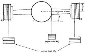
if = (revolution of input pulley C) / (revolutions of output pulleys A and B)
= (revolutions of C) /(revolution of [A+B]/2)
ηf = (output torque) / (input torque × if)
= (wo × r) / (Wi × R × if)
Method (II), (the unit inside of the car):
A simple experiment may be carried out to determine a vehicle final drive ratio and the gearbox ratios. If a starting handle is not available, a spanner may be used on the nut fitted at the nose of the crankshaft and fan pulley.
Procedure:
1- In case of rear wheel drive,
chock the front wheels and jack up one rear wheel.
In case of front wheel drive, chock the rear wheels and jack up one
front wheel.
Mark the jacked wheel’s tire and floor surface.
2- Select top gear. Rotate engine crankshaft until rear wheel had made exactly two revolutions. Note revolutions given to crankshaft.
Final drive ratio (if) = number of turns of crankshaft
3- Select and engage first gear and repeat above procedure (2) and again note exact revolutions of crankshaft.
Since the overall (total) reduction ratio it = ig × if therefore:
1st gear ratio ig1
= (number of crankshaft revolution per two crankshaft rev)/ (final drive ratio if)
4- Repeat the procedure for the other gears.
Note: When one wheel is raised off the road surface, and a standard type differential is fitted, the raised wheel will make double the normal number of revolutions.
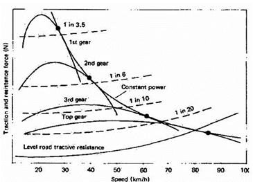
Tractive effort (TE) curves and road resistance:
|
The tractive effort curves drawn in the opposite figure following the equations below:
TE1 = Te it1 ηt1 / rw = [Te (ig1 if) (ηg1 ηf) / rw] (N)
v1 = (2 π Ne / it ) rw / 60 = [Ne rw / (9.55 it)] (m/s) =[0.377 Ne rw / it1 ] (km/h)
The tractive effort vs. velocity curve obtained from the torque vs. rpm curve. |
|