Automobile Clutch
Clutch function
Stationary idle, transition to motion and interruption of power flow are all made possible by the clutch. The clutch slips to compensate for the difference in the rotational speeds of the engine the drive train when the vehicle is being set to motion. When a change in operating conditions makes it necessary to change gears, the clutch disengages the engine from the drive train for the duration of the procedure.
|
|

The clutch is intended for general starting of the automobile from rest, disconnecting the engine form the transmission in order to shift gears, and for avoiding the effect of large dynamic loads on the transmission which appear in transient conditions and on moving on different types of roads.
The friction-clutch design, besides allowing for the main requirements (minimum clutch weight, simplicity, of construction, high reliability, and others), should ensure the following:
· Reliable transfer of engine torque to the transmission in all service conditions.
· Smooth starting of the automobile from rest and complete engagement of the clutch.
· Proper disengagement, i.e. complete disconnection of the engine form the transmission with guaranteed clearance between friction surfaces.
· Minimum moment of inertia of driven elements of the clutch, which permits smoother shifting of gears and reduces the wear of the friction surfaces in the synchronizer.
· Necessary heat rejection form friction surfaces.
· Safeguards the transmission against dynamic loads.
· Convenience and ease of control, which are estimated by the effort to be applied to the pedal and pedal movement on disengaging the clutch.
Types of Clutches
The types of clutches can be classify by:
The method of transmitting torque:
- Friction
- Hydraulic
- Automatic
The method of control:
- Manual
- Manual with booster
- Automatic
The method of creating force on pressure plate:
- Spring clutches (cylindrical, conical, and disc springs)
- Semi-centrifugal clutches (pressure is created simultaneously by springs and centrifugal forces.
- Centrifugal clutches.
The shape of friction surfaces:
- Disc
- Cone (mainly used as a secondary friction devices)
- Drum (block) (mainly use as a secondary friction devices)
The number of driven plate (disc plate clutches):
- Single-disc clutch
- Double-disc clutch
- Multi-disc clutch (mainly used in automatic transmission)
Single-disc dry clutches are simple in making and servicing; they are reliable and noted for sufficiently good disengagement and ensure effective heat removal from friction pairs. They have small mass and high wear resistance.
If the torque to be transmitted is significant, the clutch friction moment can be increased only by increasing the diameter of friction rings or the number of driven discs. The increase in ring diameter is limited by overall dimensions of the engine flywheel and the clutch release effort. Increasing the disc diameter causes its linear speed to grow, which is leads to breakage of discs under the action of centrifugal force.
Friction Clutch:
The clutch found in vehicles equipped with a manually-shifted transmission consists of a massive pressure plate, a clutch disk – featuring bonded or riveted friction surfaces – and the second friction surface represented by the engine mounted flywheel. The flywheel and pressure plate provided the thermal absorption required for the friction operation of the clutch; flywheel and pressure plate are connected directly to the engine, while the clutch disk is mounted on the transmission’s input shaft.
A spring arrangement, frequently in the form of a central spring plate, applies which joins the flywheel, pressure plate and clutch disk for common rotation; in this state, the clutch is engaged for positive torque transfer. To disengage the clutch (e.g. for shifting), a mechanically or hydraulically actuated throwout bearing applies force to the center of the pressure plate, thereby releasing the pressure at the periphery. The clutch is activated either with a clutch pedal or with an electro-hydraulic or elector-mechanical final control element.
Torque and force calculations
Torque and Power Transmitted by a clutch
 With
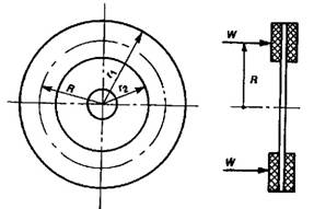
reference to the figure, let
With
reference to the figure, let
W= total spring force (N)
r1 = ro = external radius of friction (m)
r2 = ri = internal radius of friction (m)
n = number of pairs of friction surfaces
in contact
μ = coefficient of friction between disc
and driving surfaces.
Now,
Mean or effective radius, R = ½ (r1 + r2) = ½ (ro + ri)
Tangential force acting at distance R from centre of rotation,
F = μ W
\ Friction torque transmitted,
TF = F ´ R
= ½ μ W (r1 + r2)
Since there are n pars of friction surfaces in contact (for a single-plate clutch, n = 2), then the torque transmitted by a clutch is given by:
TF = ½ μ W n (r1 + r2) (N m)
If N is the rotational speed of the clutch in rev/min, then,
Power transmitted = TF ´ (2 π N/60) (W)
Area of clutch friction lining (A)
![]()
Allowable surface pressure for the lining material 0.05 N/mm2 to 0.20 N/mm2 (p)
Normal force (F)
F = A p = (π/4) (D2-d2) p
Ff = n μ F
Torque transmitted
![]() (Constant wear)
(Constant wear)
![]() (Constant
pressure)
(Constant
pressure)

μ = 0.2 : 0.3
p = 0.02 N/mm2
Tc = 50% : 100% Te max = 1.5 Te max : 2.0 Te max
|
Clutch parts |
|
|
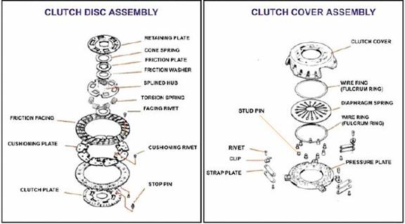
Common clutch-related components are:
Flywheel — mounts to the engine crankshaft
Clutch Disk — the friction material assembly that provides easy engagement and firm torque transference
Pressure Plate — also known as “Clutch Cover” — this is the spring-loaded surface that locks the clutch
Throw-out bearing — also known as “Release Bearing”
Pilot bearing —centers and supports the transmission input shaft (many cars do not have this bearing)
Clutch Cable — mechanical release mechanism for some vehicles Clutch Master Cylinder — force-multiplying cylinder for vehicles with hydraulic release mechanisms
Clutch Slave Cylinder — used along with a Master Cylinder for hydraulic release mechanisms
Hoses, lines, brackets, linkages, etc. — vary from vehicle to vehicle
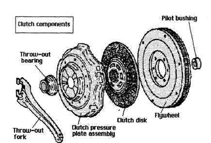
The flywheel is a large steel or aluminum disc. It acts as a balance weight for the engine, dampening engine vibrations caused by the firing of each cylinder and provides a surface that the clutch can contact. The flywheel also has teeth around its circumference for the starter motor to engage and crank the engine.
The clutch disc is a steel plate, covered with a frictional material that is sandwiched between the flywheel and the pressure plate. The center of the disc is the hub, which fits the spines of the transmission input shaft. When the clutch is engaged, the disc is “squeezed” between the flywheel and pressure plate, and power from the engine is transmitted by the disc’s hub to the input shaft of the transmission.
A pressure plate is a metal spring-loaded friction surface that is bolted to the flywheel. It has a metal cover, heavy release springs, a metal pressure surface, and a thrust ring or fingers for the release bearing. The thrust ring or fingers release the clamping force of the springs when the clutch is disengaged.
When the clutch pedal is depressed, the “Throw-out bearing” pushes the pressure plate’s release fingers. The pressure plate pulls away from the clutch disc, disengaging the clutch, thus interrupting power flow. When the clutch pedal is released and the clutch is fully engaged, the release bearing is normally stationary and does not rotate with the pressure plate.
Clutch operation is accomplished either mechanically or with a hydraulic pressure system.
If a vehicle has a mechanically operated linkage, it will incorporate either a shaft- and-lever linkage arrangement or a cable.
Systems that are made up of linkages, levers and pivot points are found primarily on older vehicles. These systems require regular lubrication and can only be designed to fit a limited range of configurations.
A cable operated clutch mechanism is relatively simple. A cable connects the clutch pedal directly to the clutch release fork. This simple design is flexible and compact. There is however, a tendency for cables to gradually stretch and eventually break due to age and wear.
On a hydraulically operated clutch, a master cylinder is usually directly operated by the clutch pedal assembly. A slave cylinder at the transmission is connected to the master cylinder by high-pressure tubing. The slave cylinder pushes either an operating lever or directly on the release bearing. Hydraulic systems require less pedal pressure and provide a smooth “liquid” feel to clutch engagement. Design configuration is very flexible and can very easily be adapted to most any required configuration.
|
|
The force exerts on the pressure plate which creates the normal force is produce from either a series of coil springs or a diaphragm spring, placed compressed between the pressure plate and the clutch cover. The diaphragm spring compared with the coil springs offers the following advantages:
- Compact, less parts, less weight, less moment of inertia.
- Suitable for high engine speeds. Coil springs bow outwards owing to centrifugal action and this lowers the spring force, it can also cause vibration owing to imbalance.
- Lower pedal force, less friction since fewer parts are needed to operate the clutch. Also the force deflection curve suits the application.
- Clamping force on friction facings does not decrease as facing wear.
- Better normal force distribution.
- Need no adjustment, less maintenance, and less assembly effort.
|
|
|
Automobile friction disc clutch |

|
|
