Axle Shafts Design
Rear axle construction
In cases where the rear suspension is non-independent, the type of axle used is either a dead axle or a live axle. The former only has to support the weight of the vehicle, where the latter has to fulfill this task and, in addition, contain a gear and shaft mechanism to drive the road wheels.
Axle shafts
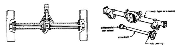
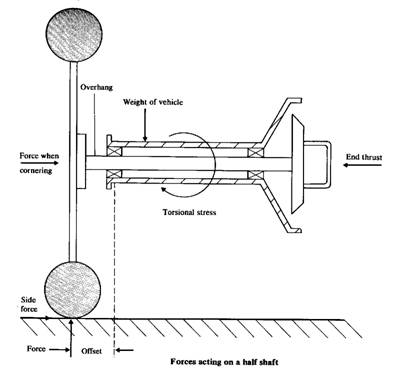
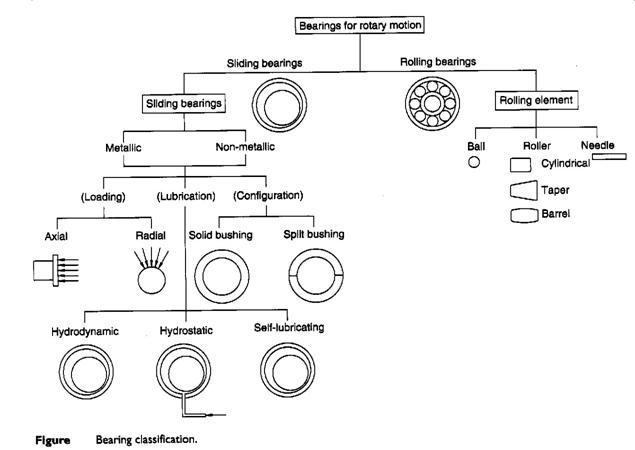
The axle shaft (half shaft) transmits the drive from the differential sun wheel to the rear hub. The arrangement of a simple rear axle can be seen in the figure, the road wheel attached to the end of the half shaft, which in turn is supported by bearing located in the axle casing. The diagram illustrates the forces acting on the rear axle assembly under a under different operating conditions.
Operating conditions
The total weight of the rear of the vehicle may exert a bending action on the half shaft. Furthermore, there is a tendency for the overhanging section of the shaft to be subject to a shearing force.
During cornering a side force acts upon the road wheel which imposes a bending load and an end thrust becomes a ‘pull’. A side force also tends to bend the overhanging section of the half shaft. Finally, under driving conditions the half shaft has to transmit the driving torque which subjects the shaft to torsional stress.
Stresses
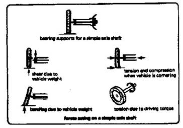
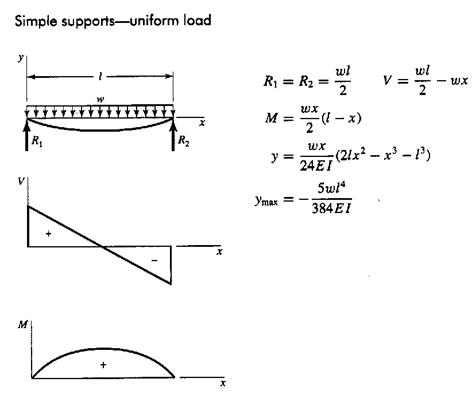
The various types may be compared by considering the stresses the shaft has to resist Fig. 1a shows a line sketch of a simple haft which is subjected to:
1- torsional stress due to driving and braking torque.
2- Shear stress due to the weight of the vehicle (Fig. 1b).
3- Bending stress due to the weight of the vehicle (Fig. 1c).
4- Tensile and compressive stress due to cornering forces.
Types of axles
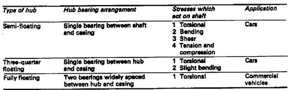
 Axle shafts are divided into three main groups
depending on the stresses to which the shaft is subjected:
Axle shafts are divided into three main groups
depending on the stresses to which the shaft is subjected:
· Semi-floating
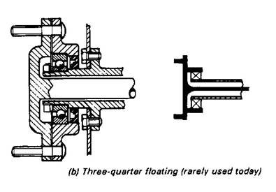
· Three-quarter floating
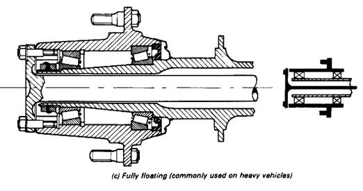
· Fully floating.
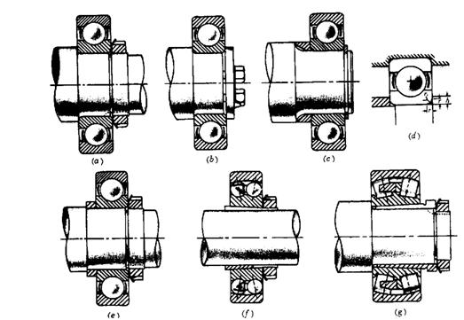
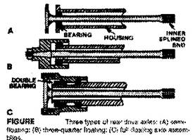
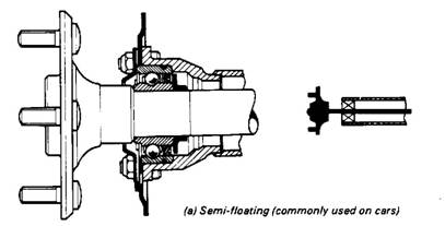
Semi-floating
Fig. 2a shows a typical mounting of an axle shaft suitable for light cars. A single bearing at the hub end is fitted between the shaft and the casing, so the shaft will have to resist all the stresses previously mentioned. To reduce the risk of fracture at the hub end (this would allow the wheel to fall off), the shaft diameter is increased. Any increase must be gradual, since a sudden change in cross-sectional area would produce a stress-raiser and increase the risk of failure due to fatigue. (Fatigue may be defined as breakage due to continual alteration of the stress in the material).
Although the final-drive oil level is considerably lower than the axle shaft, the large amount of ‘splash’ would cause the lubricant to work along the shaft and enter the brake drum. Sealing arrangements normally consists of an oil retainer fitted at the hub end (the lip of the seal is positioned towards the final drive). The half shaft in this assembly required to be able to withstand the torsion load involved in driving the road wheel, and bending loads in both the horizontal and vertical planes plus the percentage of car weight on the wheel.
Three-quarter floating
Having defined the semi-and the fully floating shaft, any alternative between the two may be regarded as a three-quarter floating shaft. Fig. 2b shows a construction which has a single bearing mounted between the hub and the casing. The main shear stress on the shaft is relieved but all other stresses still have to be resisted. The half shaft must withstand bending loads due to side thrust when cornering and, of course, at the same time transmit driving torque.
Fully floating
This is generally fitted on commercial vehicles where torque and axle loads are greater.
The construction shown in Fig. 2c consists of and independently mounted hub which rotates on two bearings widely spaced on the axle casing. This arrangement relieves the shaft of all stresses except torsional, so the construction is very strong. Studs connecting the shaft to the hub transmit the drive and when the nuts on theses studs are removed, the shaft may be withdrawn without jacking up the vehicle. The shaft is to transmit only the driving torque to the rear wheel.
Axel shaft material
A tough, hard material must be used to withstand the various stresses, resist spline wear and provide good resistance to fatigue. A medium carbon alloy steel containing such elements as nickel, chromium and molybdenum is the usual choice.
Calculation of axle shafts
The following forces act on a moving wheel:
· The torque due to the traction or braking force (Tw and Tb)
· The traction or braking force (Fw and Fb)
· The lateral force Fy when the vehicle makes a turn or skid
· The normal reaction Rw
Simultaneous appearance of maximum longitudinal and transverse forces at the wheel road contact is not possible, for joint action is restricted by the adhesion force
![]()
The loading conditions of axle shafts and beams reduce to the following three cases:
1- Rectilinear motion
The longitudinal force (Fw or Fb) attain its maximum value equal to Rw φ, Maximum torque is
where:
Tw = wheel torque
Te max = maximum engine torque
ig = gearbox ratio (1st gear)
if = final drive ratio
kd = dynamic factor
kl = the coefficient of differential locking
ma = automobile mass accounted for the driving axle
g = 9.81 m/s2
wt = transferred weight
![]()
where
φ = coefficient of adhesion (0.8)
* In this case, Fy = 0
2- Skidding of automobile
In this case a lateral force and normal reaction are acting on the wheel. Assume that the longitudinal force Fw = 0. The largest lateral force- centrifugal force- whose value is limited by the wheel-road grip equals
![]()
The vertical reactions and lateral forces of the inner and outer wheels are
![]()
where
v = vehicle speed (km/h)
R = radius of turn of the road
t = wheel track width
φ = coefficient of road adhesion during sidewise skidding =1.0
+ = plus sign is used for the axle shaft of the wheel which is inner relative to the skidding direction, and the negative sign, the outer wheel.
3-Driving wheels overcome irregularities
Here, only the vertical force is accounted for
![]()
where
kdr = is the dynamic factor of road;
for cars, kdr = 1.75; for trucks, kdr= 2.50
-The axle shaft dimensions are determined for the most dangerous case of loading. For s semi-floating axle the dangerous cress section lies in the bearing installation zone. For the first condition, the equivalent stress due to bending and torsion is
where
d = the axle shaft diameter
b = the overhanging length
During skidding the following bending moments and stresses act on the axle shaft
Mi = Rw i b – Fy i rw;
Mo = Rw o b + Fy o rw
![]()
where
rw = wheel radius
(the upper sings are used for the inner axle shaft, and the lower sign, for the outer axle shaft relative to the skidding direction).
-When the driving wheels overcome an irregularity, the bending stress is
- The floating axle is calculated only for torsion at the maximum traction force
![]()
The axle shaft is calculated also for the maximum twist angle
![]()
where
L = the length of the axle shaft
G = the shear modulus
J = the moment of inertia of the cross section of axle shaft
sb = 55 MPa for shafts without keyway
40 MPa for shafts with keyway
* The permissible twist angle is θ = 8o for 1 m length of the shaft.
# Number of splines of the axle shaft is form 10 (for cars) to 18 (for trucks)
# the shaft factor of safety = 2.0- 2.5
Critical Speeds of Shaft
All rotating shafts, even in the absence of external load, deflect during rotation; the magnitude of the deflection depends upon the stiffness of the shaft and its supports, the total mass of the shaft and attachment parts, the imbalance mass with respect to the axis of rotation, and the amount of damping in the system.
Shafts of constant cross section:
Example:
Find the half axle critical speed, the half axle has the following dimensions the length between bearings is 0.6 m and its diameter is 25 mm. The unit weight of shaft materials is 76.0 kN/m3, E = 200 GPa.
Calculation of wheel-hub bearings
For the bearings of the driving axle with semi-floating axle shafts (as seen in the figure),
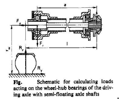
the loads on wheel bearing are calculated using the following formulas:
Straight-line motion
Fr = Rz l / a; Fa= 0
Curvilinear motion
Fr o = Rz o l / a + Ry o rw / a; Fa o = Ry o
Fr i = Rz o l / a – Ry i rw / a; Fa i = Ry i
Necessary service life of bearings (in millions of revolutions) is ascertained based on the specified life of the automobile with due consideration of overhaul periods.
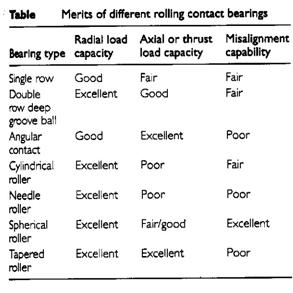
Bearing Classifications
Rolling Bearings versus Journal Bearings:
|
Features |
Ball Bearings |
Journal Bearings |
|
Starting torque |
High (advantage) |
Low |
|
Quit operation |
Noisy at high speed |
Quit operation |
|
Space Limitation |
Preferable when the axial dimension are limited |
Preferable when the radial dimension are limited |
|
Electrical insulation |
- |
Oil film provides insulation |
|
Failure warning |
Becoming noisy when failure is imminent |
Failure is sudden |
|
Thrust load |
Can carry combination of radial and thrust loads |
- |
|
Clearance |
Much less the journal bearing, more accurate position (gears) |
- |
|
Lubrication problem |
Not sensitive |
Very sensitive |
|
Overload |
Can take high overloads for short time |
- |
 Bearing Selection:
The selection of an appropriate bearing for a given task, whoever, in an involved activity, which needs to take into account, amongst other factors:
- load
- speed
- location
- size
- cost
- starting torque
- noise
- lubrication supply
Definitions:
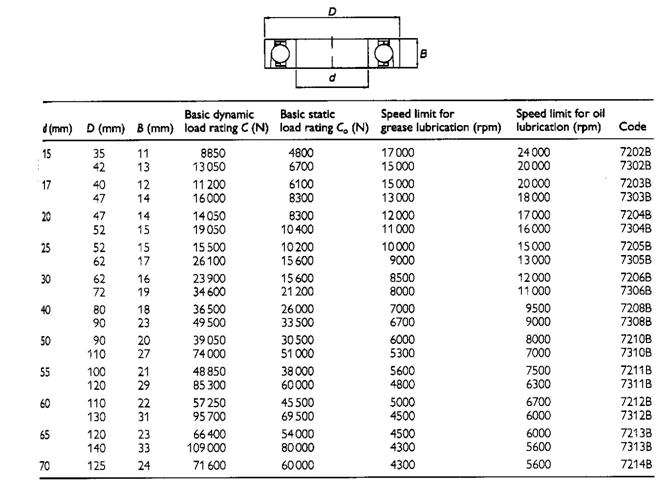
The basic static load rating, Co,
is the load the bearing can withstand without any permanent deformation of any component.
The basic dynamic load rating, C,
is the constant radial load which a bearing can endure for 1x10⁶ revolutions without evidence of the development of fatigue in any of the bearing components.
The life of a ball bearing, L,
is the number of revolutions (or hours at some constant speed), which the bearing runs before the development of fatigue in any of the bearing components.
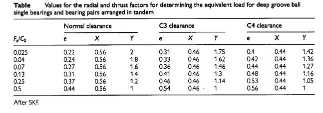
The equivalent load, P,
is defined as the constant radial load which if applied to a bearing would give the same life as that which the bearing would attain under the actual conditions of load and rotation.
P = VXR + YT
Where:
P = equivalent load (N);
V = 1.2 if mounting rotates is recommended
= 1.0 if shaft rotates;
X = radial factor (given in bearing catalogues), see table 2 for example data;
Y = thrust factor (given in bearing catalogues), see table 2 for example data;
T = applied thrust load (N)