Suspension Formulas

Where b is the width of spring blade (m), L is the distance between the eyes of the spring when laden (m), t is the thickness of the blade (m), n is the number of blades, and E is the modulus of elasticity, which (modified to allow for internal friction) is 159 x 106 kN/m2.
For a torsion bar, the spring rate is given as the twisting moment per angular deflection. When a lever is added, this can be converted into a rate for the vertical deflection of the end of the lever.
Spring rate (torsion bar, for deflection at end of lever)
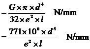
Where G is the modulus of rigidity, which is 78.5 x 10⁶ kN/m2 in this case, d is the diameter of the torsion bar (m); l is the effective length of the torsion bar (m), i.e. half the length of the bar for an anti-roll bar, and e is the length of the lever (m).
Spring rate (coil spring)
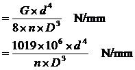
where G is the modulus of rigidity, which is 81.5 x 10⁶ kN/m2 in this case, d is the wire diameter (m), n is the number of free coils, and D is the mean coil diameter (m). To find the number of free coils it is necessary to subtract the number of dead coils form the total number of coils. The dead coils are those that provide the abutment and so cannot be deflected, usually 1.5 to 2 coils.
Wheel rate:
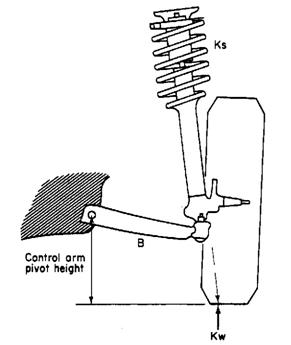
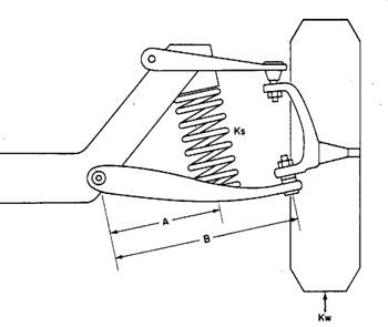
The wheel rate is not the same as the spring rate, and depends on the effective leverage, or the separation of the springs relative to the track. Thus if the distance from the centre-line of the car to the spring on a beam axle is a, and the distance from the centre-line of the car to the centre-line of the wheel (i.e. half the track) is b, as shown in Figure 1 (a) then :
![]()
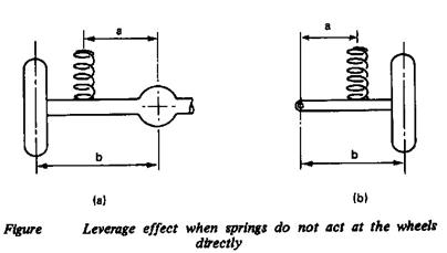
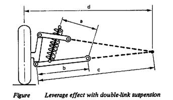
With independent suspension the formula is similar except that b is the length of the suspension arm and a is the distance form its pivot to the axis of the spring (Figure 1 (b)). With double-wishbone suspension the formula is modified to take into account the effects of the other whish bone on the geometry. The formula becomes:
Wheel rate CW = (CS × a2× c2)/(b2×d2) N/mm
Where a, b, c, and d are as shown in Figure 2.
![]() kw
= ks
kw
= ks
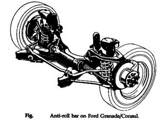
Anti-roll bars
![]()
Where
ke = equivalent rate
kw = wheel rate
ka = anti-roll bar rate measured at the wheel
Example:
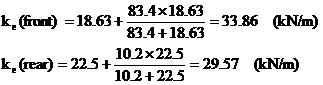
The Porsche 928 is provided with a strong anti-roll at the front and a relatively weak one at the rear. The appropriate data are as follows:
Front Rear
Wheel rate (kN/m) 18.63 22.55
Anti-roll rate (at wheel) (kN/m) 83.4 10.2