
Vehicle power source unit:
- Internal combustion engine (fuel powered)
- Electric motor (battery powered)
- Hybrid car (Electric motor + internal combustion engine)
Engine definition:
Engine is a machine that converts energy into mechanical force or motion. Such a machine distinguished from an electric, spring-driven, or hydraulic motor by its use of a fuel.
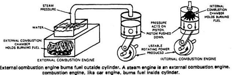
Internal and External Combustion Engine Classifications:
- External combustion engines burns its fuel on the outside. As shown in the figure, a steam engine is the most typical example of an external combustion engine. The resulting heat is used to produce steam. The steam is then piped into the engine cylinder to produce pressure to operate the engine piston.
- Internal combustion engines burns its fuel on the inside. An automotive engine is an internal combustion engine because its fuel is ignited and burns in the cylinder. Most other engines (rotary, turbine, etc.) are also internal combustion engines.
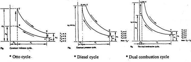
IDEAL HEAT ENGINE GAS CYCLES:
In thermodynamics,
heat engines are often modeled using a standard engineering model such as the Otto cycle.
The theoretical model can be refined and augmented with actual data from an
operating engine, using tools such as an indicator
diagram. Since very few actual implementations of heat engines exactly match
their underlying thermodynamic cycles, one could say that a thermodynamic cycle
is an ideal case of a mechanical engine.
Real cycle of SI Engine:
Most modern internal combustion engines work on a four-stroke cycle; that is, a complete cylinder cycle consists of four discreet strokes, as described below. Other types of engines can have very different stroke cycles
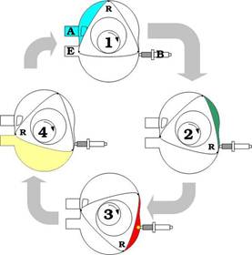
Four-stroke-cycle engine:
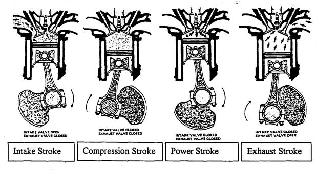
A stroke is the action of a piston travelling the full length of its engine cylinder in one direction. The stroke length is determined by the cranks on the crankshaft. Stroke can also refer to the distance the piston travels (from top dead center (TDC) to bottom dead center (BDC)).
* Intake (induction or inlet) stroke: The intake valve has opened. The piston is moving downward, drawing a mixture of air and gasoline vapor into the cylinder.
* Compression stroke: The intake valve has closed. The piston is moving upward, compressing the mixture.
* Power stroke: The ignition system has delivered a spark to the spark plug that ignites the compressed mixture. As the mixture burns, high pressure is created which pushes the piston downward.
* Exhaust stroke: The exhaust valve has opened. The piston is moving upward, forcing the burned gases from the cylinder.
|
Two-stroke-cycle engine: A two-stroke cycle engine is similar to an automotive four-stroke engine, but it only requires one revolution of the crankshaft for a complete power-producing cycle. Generally, two-stroke cycle engines are NOT used in automobiles because they: |
|
|
- Produce much exhaust pollution - Have poor power output at low speeds - Require more service than a four-stroke - Are not as fuel efficient as a four- stroke - Must have motor oil mixed into the fuel.
|
|

|
Wankel (rotary) engine A Wankel engine, also termed a rotary engine, uses a triangular rotor instead of conventional pistons. The rotary turns or spins inside a specially shaped housing. One complete cycle (all four storks) takes place every time the rotor turns once. A rotary engine is very powerful to its size. Also because it spins- rather than moves up and down- engine operation is very smooth and vibration free. A complicated emission control is needed to make the rotary engine pass emission standards. |
|
Gas Turbine:
A gas turbine uses burning and expanding fuel vapor to spin fan type blades. The “fan blades” are connected to a shaft that can be used for power output.
The gas turbine is capable of high efficiency- much higher than a conventional piston engine. It can burn many types of fuel: gasoline, kerosene, or oil. A gas engine can produce tremendous power to its size. Because of the spinning action, its power output is very smooth. The gas turbine is not presently in use in automobiles because of its high manufacturing costs.
|
|

Internal combustion engines fuel:
- Fossil fuel: these are cool, natural gas, and fuels derived from crude oil (for example petrol and diesel) and have been formed long periods of time from ancient organic matter.
Natural gas is a fossil fuel comprised mostly of methane, is one of the cleanest burning alternative fuels. It can be used in the form of compressed natural gas (CNG) or liquefied natural gas (LNG) to fuel cars and trucks.
Dedicated natural gas vehicles are designed to run on natural gas only, while dual-fuel or bi-fuel vehicles can also run on gasoline or diesel.
Methanol is an alcohol fuel that’s derived primary from coal, typically made from natural gas. Most fuel methanol is sold as a blend of 85% methanol with 15% unleaded premium gasoline, whence "M85".
Ethanol is produced from corn and other crops and produces less greenhouse gas emissions than conventional fuels. Blend of 85% anhydrous with 15% gasoline ethanol called E85 fuel. Concerns about vapor lock, cold starts, and flame visibility like those for methanol have led to the same standard blend of 85% alcohol with 15% gasoline.
Biodiesel is derived from vegetable oils and animal fats. It usually produces less air pollutants than petroleum-based diesel.
Low-level biodiesel blends: when biodiesel is blended with petroleum diesel, it produces a fuel is compatible with diesel engines. Blind like B2 (2% biodiesel, 98% diesel) and B5 (5% biodiesel, 95% diesel) are becoming increasingly common as drivers become aware of the benefits.
Propane: also called liquefied petroleum gas (LPG), is a clean-burning fossil fuel
that can be used to power internal combustion engines.
Compressed
natural gas (CNG)
is like liquefied petroleum gas (LPG) in many ways. It is very easy on
the engine, giving longer service life and lower maintenance costs. CNG is the
least expensive alternative fuel (except electricity)
when you compare equal amounts of fuel energy. The high octane rating of
natural gas allows the CNG to use a very high compression ratio and produce
more power than stock gasoline versions.
Liquefied natural gas (LNG) comes from the same sources as compressed natural gas (CNG).
Hydrogen: can be burned in an internal combustion engine or can be used in a fuel cell. Hydrogen does not occur free in nature; it can be made by "re-forming" natural gas or another fossil fuel, or by using electricity to split ("electrolyze") water into its components of oxygen and hydrogen. It is not a very good fuel for an internal combustion engine, being prone to preignition, though BMW, Mazda, and Ford have done some tests; the most efficient way to use it is in fuel cell vehicles, but these are still in the demonstration stage.
Electricity: can be made by many means, from the burning of high-sulfur coal to pollution-free photovoltaic cells (or solar cells). Electric vehicles are generally divided into battery (plug-in vehicles) and hybrid classes, depending on whether the electricity is generated off-board and stored in a battery or generated by a small on-board power plant. Hybrid electric vehicles can be designed to run on any fuel, including gasoline or diesel as well as alternative fuels, and can best be thought of as highly-efficient gasoline, diesel, or alternative-fueled vehicles.
* Bi-fuel vehicles, where two fuels are stored in separate tanks and the engine runs on one fuel at a time, for example (CNG), (LPG) or (hydrogen). Two types of fuel are stored in the car, but only one is delivered to the engine at any given time. Either a manual switch or some type of automatic sensor will tell the fuel injection system which fuel should be used.
* Flexible-fuel vehicle (FFV)or dual-fuel vehicle (colloquially called a flex--fuel vehicle) is an alternative fuel vehicle with an internal combustion engine designed to run on more than one fuel, usually gasoline blended with either ethanol or methanol fuel, and both fuels are stored in the same common tank. Flex-fuel engine are capable of burning any proportion of the resulting blend in the combustion chamber as fuel injection and spark timing are adjusted automatically according to the actual blend detected by electronic sensors.
Gasoline and diesel engine classifications:
A gasoline (Petrol) engine or spark ignition (SI) burns gasoline, and the fuel is metered into the intake manifold. Spark plug ignites the fuel. A diesel engine or (compression ignition Cl) bums diesel oil, and the fuel is injected right into the engine combustion chamber. When fuel is injected into the cylinder, it self ignites and bums.
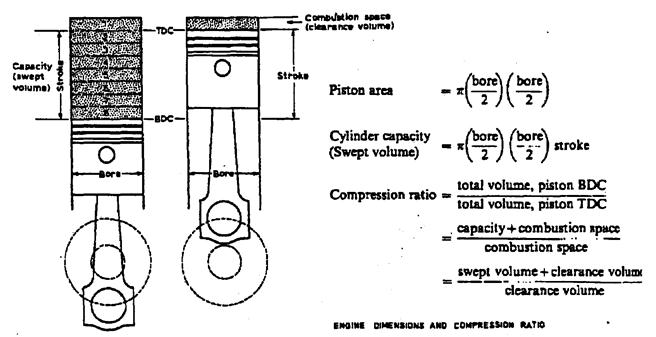
Engine swept volume (engine displacement, engine capacity):
Is the volume swept by all the pistons inside the cylinders of an internal combustion engine in a single movement (stroke) from top dead centre (TDC) to bottom dead centre (BDC). It is commonly specified in cubic centimeters (cc), liters (l), or (mainly in North America) cubic inches displacement (CID). Engine displacement does not include the total volume of the combustion chamber.
![]()

where:
D = Cylinder bore diameter
L = Stroke
Ve = Engine swept volume -in liters or cubic centimeters
(liter, or cm3 (cc))
Vs = Cylinder swept volume
n = number of cylinders
Variable displacement engine:
Variable displacement is an automobile engine technology that allows the engine displacement to change, usually by deactivating cylinders, for improved fuel economy. The technology is primarily used in large, multi-cylinder engines. This technology allow for more fuel efficient car without sacrificing peak power, the driver has access to the full towing and payload capacities when needed, but also the fuel economy of a smaller displacement engine when the vehicle is not under full load.
GM refers to its system as Displacement on Demand (DOD) on its midsize SUVs. A similar approach used by Chrysler in the Hemi V-8 is called Multiple Displacement System (MDS), which is available on the company's trucks, SUVs and some passenger cars.
Bore/stroke ratio:
In a reciprocating piston engine, the
stroke ratio, defined by either bore/stroke ratio (B/S) or stroke/bore ratio
(S/B), is a term which is used to describe the ratio between the diameter of
the cylinder bore and the length of the piston stroke within its cylinders.
Square,
under-square and over-square engines
The
following terms describe the naming conventions for the various configurations
of the relationship ratio between the diameter of the cylinder bore and the
length of the piston stroke within the cylinders of a piston engine.
An engine is described as a square engine when it has equal bore and
stroke dimensions, giving a bore/stroke value of exactly 1:1.
An engine is described as oversquare or short-stroke if its
cylinders have a greater bore diameter than its stroke length - giving a ratio
value of greater than 1:1. This configuration decreases the torque but allows
the engines to run at higher speeds and in fact develop greater peak power.
This is the most common engine design for automotive engines.
An engine is described as undersquare or long-stroke if its
cylinders have a smaller bore (width, diameter) than its stroke (length of piston
travel) - giving a ratio value of less than 1:1. This configuration increases
the displacement and therefore the torque of the engine, but may reduce the
peak speed at which it is safe to run. This is the most common engine design
for large industrial and tractor engines.
Rod/stroke ratio
To determine a motor's rod/stroke ratio, divide rod length
(distance in millimeters from the center of the big and small ends) by stroke.
Most engine builders shoot for a ratio between 1.5:1 and 1.8:1 on a
street motor.
The rod/stroke ratio affects several engine dynamics, including piston
speed and acceleration, piston dwell at top dead center and bottom dead center,
piston side loads, cylinder loading and bearing loads. Many of these elements
play roles in engine aspiration, combustion and wear.
Generally, a lower ratio means a high rod angle, creating greater potential for
accelerated wear to cylinder walls, pistons and rings. A low enough ratio, due
to the severity of its rod angle, can drive a piston right into the cylinder
wall.
Higher ratio engines, air does not fill the
intake ports with the same velocity, and there is less demand for the ports to
flow as well since there is more time to fill and scavenge the cylinder. This
typically means stagnant airflow at low revs and weaker torque.
Compression ratio (CR) of an internal-combustion engine is a value that represents the ratio of the volume of its combustion chamber from its largest capacity to its smallest capacity. It is a fundamental specification for many common combustion engines.
In a piston engine it is the ratio between the volume of the cylinder and combustion chamber when the piston is at the bottom of its stroke, and the volume of the combustion chamber when the piston is at the top of its stroke.
During this process the pressure and temperature of the gas rise. The ratio of volume before and after compression is called the compression ratio:
![]()
where:
r = compression ratio
Vs = Swept volume (cylinder volume),
Vc = clearance volume
Compression ratio and overall pressure ratio are interrelated as follows:
|
Compression ratio |
2:1 |
3:1 |
5:1 |
10:1 |
15:1 |
20:1 |
25:1 |
35:1 |
|
Pressure ratio |
2.64:1 |
4.66:1 |
9.52:1 |
25.12:1 |
44.31:1 |
66.29:1 |
90.60:1 |
145.11:1 |
Also, the pressure ratio is defined as the pressure increase = pTDC /pBDC .
Typical compression ratios:
Petrol (gasoline) engine:
The compression ratio in a gasoline or petrol-powered engines will usually in the range of 11:1. The limit on compression ratio is due to engine combustion problems; pinging (detonation). To avoid this problems a gasoline with high-octane number should be used.
In engines with a 'ping' or 'knock' sensor and an electronic control unit, the CR can be as high as 13:1.
In a turbocharged or supercharged gasoline engine, the CR is customarily built at 9.32:1 or lower.
Ethanol and methanol engines can take significantly higher compression ratios than gasoline. Racing engines burning methanol and ethanol fuel often exceed a CR of 15:1.
In engines running exclusively on LPG or CNG, the CR may be higher, due to the higher octane rating of these fuels.
In an auto-ignition diesel engine, the CR ratios over 22:1 are common. The appropriate compression ratio depends on the design of the cylinder head. The figure is usually between 14:1 and 16:1 for direct injection engines and between 18:1 and 23:1 for indirect injection engines.
Generally, a high compression ratio will increase engine power and fuel economy, but will increase harmful exhaust emission (NOx) levels.
Preparation of fuel air mixture (gasoline engine):
* High calorific value (Heat value): (Benzene (Gasoline) 40000 kJ/kg, Diesel 45000 kJ/kg).
Variable compression ratio (VCR) engines:
A variable compression ratio (VCR) engine is able to operate at different compression ratios, depending on the particular vehicle performance needs. The VCR engine is optimized for the full range of driving conditions, such as acceleration, speed, and load. At low power levels, the VCR engine operates at high compression to capture fuel efficiency benefits, while at high power levels, it operates at low compression levels to prevent knock.
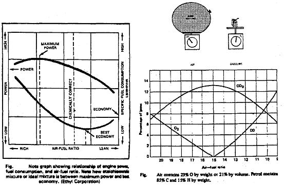
* Air-fuel ratio (AF ratio) for gasoline engine: A chemically correct air-fuel ratio is called stoichiometric mixture. It is an ideal ratio of around 14.7:1 (14.7 parts of air to 1 part fuel by weight). Under steady-state engine condition, this ratio of air to fuel would assure that all of the fuel will blend with all of the air and be burned completely.
A gasoline engine has an air-fuel ratio of between 18:1 at idle speed and 12:1at full load.
A lean fuel mixture containing a lot of air compared to fuel, will give better fuel economy and fewer exhaust emissions (i.e. 17:1).
A rich fuel mixture: with a larger percentage of fuel, improves engine
power and cold engine starting (i.e. 8:1).
However, it will increase emissions and fuel consumption.
* Gasoline density = 737.22 kg/m3, air density (at 20o) =
1.2 kg/m3
The ratio 14.7 : 1 by weight equal to 14.7/1.2 : 1/737.22 = 12.25 : 0.0013564
The ratio is 9,030 : 1 by volume (one liter of gasoline needs 9.03 m3 of air to have complete burning).
Diesel engine: air-fuel ratios in a diesel engine vary from around 100:1 (100 parts air to 1 part fuel) at idle speed to 20:1 at full load.
* Fuel atomization: refers to how the fuel injector or carburetor breaks up liquid gasoline into tiny droplets.
= Volume of air taken into cylinder / Maximum possible volume in cylinder
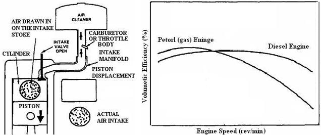
* Volumetric efficiency depends upon throttle opening and engine speed as well as induction and exhaust system layout, port size and valve timing and opening duration.
Volumetric efficiency of naturally aspirated automobile and aircraft reciprocating engines may be 85–90% at rated speed. Super charging or turbo charging increases volumetric efficiency, giving values over 100%.
Methods to increase the volumetric efficiency (VE):
There are several standard ways to improve volumetric efficiency:
* Use larger valves or multiple valves.
* Streamlining the ports.
* Arranged air intakes and tuned exhaust systems to push air into and out of the cylinders, making use of the resonance of the system.
* Use variable valve timing,
variable valve timing with inelegance and variable valve timing –intelligent by
electric motor (VVT, VVT-i, VVT-iE), at higher speeds the engine needs the
valves open for a greater percentage of the cycle time to move the charge in
and out of the engine.
Use variable valve timing and lift (VVTL, VVTL-i), is a version that can alter
valve lift (and duration) as well as valve timing.
Use dual valve timing for both the inlet and exhaust valves (Dual VVT).
* Use supercharger or turbocharger.
Volumetric efficiency is
affected by the following fuel, engine design, and engine operating variables:
1. Fuel type, fuel/air ratio, fraction of fuel vaporized in the intake system,
and fuel heat of vaporization.
2. Mixture temperature uninfluenced by heat transfer.
3. Ratio of exhaust to inlet manifold pressures.
4. Compression ratio.
5. Engine speed.
6. Intake and exhaust manifold end port design.
7. Intake and exhaust valve geometry, size, lift, and timings
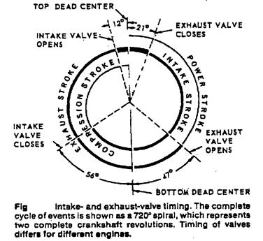
Valve Timing:
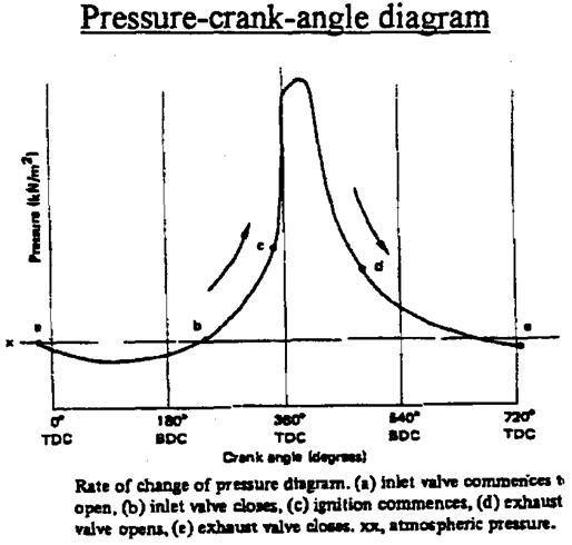
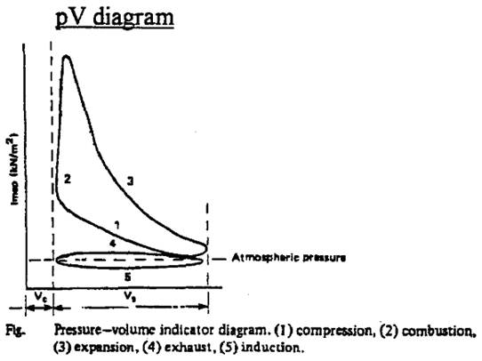
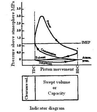
Engine indicator diagrams:
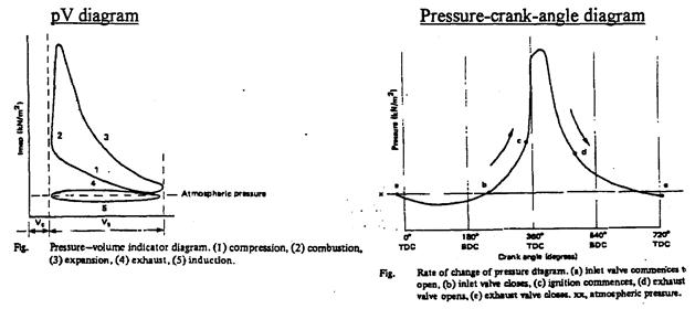
Indicated mean effective pressure (imep) or (IMEP):
The mean effective pressure is a quantity related to the operation of an internal combustion engine and is a valuable measure of an engine's capacity to do work that is independent of engine displacement. When quoted as an indicated mean effective pressure or imep it may be thought of as the average pressure over a cycle in the combustion chamber of the engine.
* The highest mean effective pressure obtained without supercharging, and using petrol as fuel is between 896 and 1103.6 kN/m2.
Indicated power (Pi):
This is the power that would be available at the crankshaft if a mechanical efficiency of 100% was possible. The term “indicated” is derived from the use of engine indicators and their diagrams from which indicated power could be calculated.
Total average force per revolution [F] (N or kN) = p . A=
![]()
Total work done per revolution [W] (N m or J, kN m, kJ) = F . L =
![]()
Total power (work done per second) [P] = J/sec (W) = W/t
![]()
Where:
imep = average or indicated mean effective pressure (N/m2) or kN/m2
A = area of the piston crown (m2)
n = number of engine cylinders
L = piston or engine stroke (m)
N/2 = number of firing impulses per minute per cylinder (4-stroke cycle)
L A n = total swept volume of engine, or engine capacity (m3)
Pi = indicated power (N m/s or W)
Ve = engine capacity (m3)
k = number of revolution per cycle
(for a 4-stroke engine k=2, for a 2-stroke engine k=1)
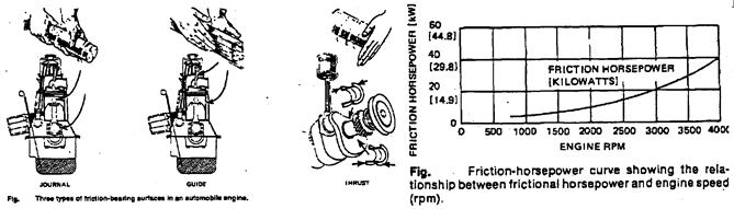
Engine friction:
Brake power (Pb):
The brake power (net power) is the engine’s power as measured at the crankshaft at a specified rpm. The engine brake power is obtained using a brake dynamometer at engine full throttle.
Diesel engine power:
A diesel engine, however, does not produce as much horsepower as a gasoline engine of equal size. Operating speeds are much lower and parts must be made heavier and stronger to withstand compression ignition.
Brake mean effective pressure (BMEP):
It is very effective yardstick for comparing the performance of one engine to another, and for evaluating the reasonableness of performance claims or requirements. The BMEP is purely theoretical and has nothing to do with actual cylinder pressures. It is simply an effective comparison tool.
BMEP is the proportion of the IMEP to perform external work at the engine crankshaft. BMEP is calculated from the brake power, and is smaller than the IMEP by the amount of pressure required to overcome the engine’s friction and pumping losses. Engines of different design and capacity can be compared accurately for performance from their ability to develop good BMEP figures. BMEP units are N/m2 or kN/m2
Brake mean effective pressure (BMEP) typical values:
- Naturally aspirated spark-ignition engines: maximum values are in the range 8.5 to 10.5 bar (850 to 1050 kPa; 125 to 150 lbf/in2), at the engine speed where maximum torque is obtained. At rated power, bmep values are typically 10 to 15% lower.
- Turbocharged automotive spark ignition engines: the maximum bmep is in the 12.5 to 17 bar range (1.25 to 1.7 MPa; 180 to 250 lbf/in2).
- Naturally aspirated four-stroke diesels: the maximum bmep is in the 7 to 9 bar range (700 to 900 kPa; 100 to 130 lbf/in2).
- Turbocharged automotive four-stroke diesels: the maximum bmep is in the 14 to 18 bar (1.4 to 1.8 MPa; 200 to 269 lbf/in2) range.
Mechanical efficiency (ηm):
Mechanical efficiency (ηm) = brake power (Pb)/indicated power (Pi)
Thus
brake power = indicated power. ηm , (Pb = Pi ηm)
brake power = imep . ηm .L A n (N/2) /60 (W) = (imep. ηm). Ve (N/2)/60 (W)
The pumping losses of the engine pistons, and the friction between their rings and the cylinder walls, account for the greater part or percentage of the lost work and power.
The main factors which contribute to the lost power are:
1. the type of materials used and their surface finish;
2. the loading between materials in contact under boundary lubrication conditions;
3. the rubbing speeds.
4. the engine compression ratio;
5. revolution per minute;
6. the throttle position;
7. windage. Air resistance increases in proportion to the square of the speed. The flywheel, clutch, generator and engine-operated cooling fan all introduce windage;
8. the churning of the lubricating oil.
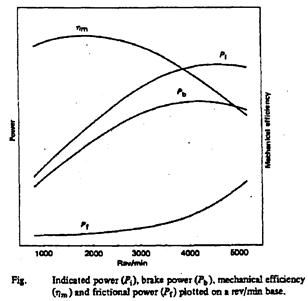
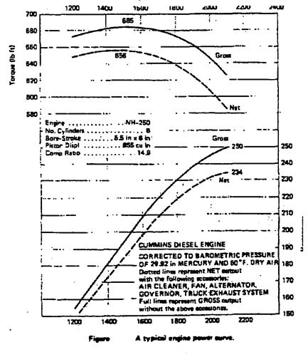
* From the figure it can be seen that the indicated power (Pi) is somewhat higher than the brake power (Pb) throughout the rev/min range, but not proportionally higher. If the vertical distance between the two curves is measured at each revolution point, this distance will represent the power lost to pumping and friction at that engine speed (friction power Pf). As engine speed rises so the losses increase, hence the increasing divergence between the brake power and indicated curve lines.
Engine torque :
Torque (T) is a turning moment (N m) and is dependent on the pressure produced within the engine cylinders, the piston crown area upon which the effective pressure (bmep) is applied, and the crankshaft angle or effective radius. Engine capacity thus plays a large part in torque production. Doubling the engine’s capacity (swept volume Ve) will almost double the engine torque.
When engine testing with a dynamometer, the load lifted is situated at end of the dynamometer torque arm:
thus torque T = w . R (Nm)
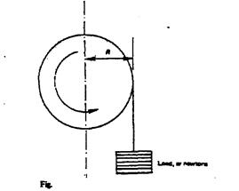 The work done in one revolution is calculated
as follows (see figure). If the brake load w was moved through one revolution
(2p) 360o with the radius or torque arm of R
(m), the work done in one revolution:
The work done in one revolution is calculated
as follows (see figure). If the brake load w was moved through one revolution
(2p) 360o with the radius or torque arm of R
(m), the work done in one revolution:
W = w . π R (N m) or J
= T . 2π
(N m) or J
where:
T = w . R
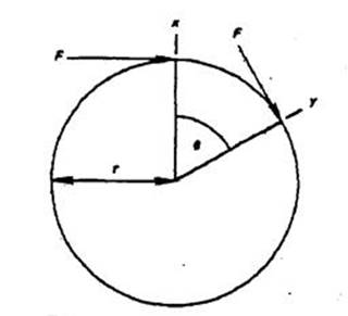
Torque and the crankshaft angle
Work is also accomplished when the torque is applied through an angle. Distance xy (see figure, is equal rθ) where θ is the angle through which the crankshaft moves, in radians.
torque = force . radius =F. r
work done = F . distance xy =F . r θ = T . θ
work done per one revolution (2π) = T . 2π (J) or N m
Engine brake power (Pb):
This is the power developed at the crankshaft or flywheel. The term brake originated from the method used to determine an engine’s power output by measuring the torque using some form of friction dynamometer. In early days of engine design the flywheel was often used for the brake dynamometer. Often quoted brake power figures do not indicate whether they are gross or net.
An engine connected to a modern test bench is generally without such items as cooling fan, coolant pump and radiator, dynamo and clutch unit and is connected to the large test bench exhaust system. Thus some 10-15% more power is often possible under these conditions (gross power) compared to the ‘under the bonnet’ performance (net power).
Engine power-to-weight ratio:
Engine power-to-weight ratio (or specific power or power-to-mass ratio) is a calculation commonly applied to engines and mobile power sources to enable the comparison of one unit or design to another. Power-to-weight ratio is a measurement of actual performance of any engine or power sources.
The power-to-weight ratio (Specific Power) formula for an engine (power plant) is the power generated by the engine (pick value) divided by weight of the engine as follows
![]()
4-stroke gas engine 0.25-0.35 kW/kg, Wankel engine 1.5 kW/kg
Power to weight ratio for the Rotapower engine is 75% better than two-stroke engines, 250% better than four-stroke piston gasoline engines and 600% better than diesel engines. It has been operated successfully on gasoline, kerosene, alcohol, diesel and natural gas. With only two moving parts, cost and maintenance are projected at well below four stroke piston engines.
Specific engine output (Engine power/unit displacement):
* On the Continent, the DIN rating is used, which confirms the engine’s performance with all its accessories as fitted to the chassis together with correction for normal temperature and pressure. in the USA the SAE rating method is adopted which in effect is the gross engine output.
Power is the rate of doing work = work done/time taken (Joules/sec) or Watts
= force . distance / time taken (t seconds)
= F . x y/t =F . r θ/t =T . θ/t = T ω
Note:
ω = θ/t = angular velocity in radians/second = 2π N/60
where:
N = engine rev/min
Brake power per one revolution = Work done per one revolution =T 2π
Work done was previously stated as equal to (imep ηm LAn/2) therefore
T 2π = (imep ηm) LAn/2
T = imep . LAn/4π = (imep ηm). engine swept volume / 4π
also brake power Pb = T ω =T . 2π N/60
T= Pb . 60/(2π N) = . Ve Ne/(60 . 2) . 60/(2π Ne) =
T= (imep ηm) Ve / (2π . 2) = bmep Ve / (2π .2)
Pb = bmep . engine swept volume . number of effective stroke / s
* indicated power = brake power + friction power
Pi = Pb + Pf
Mechanical efficiency % = ηm = brake power/indicated power = (Pi/Pb) . 100 %
* bmep (imep ηm) is an indication of engine efficiency regardless of capacity or engine speed; 1000 kPa represent high efficiency.
Fuel consumption (FC)
The fuel an engine consumes can be measured by volume or by mass. By volume the units are cm3 liters per second, minute or hour (1000 cm3 = 1 liter). By mass the units are kg per second, minute or hour (1 liter of water = 1 kg).
Liters × relative density of the fuel = kg of fuel
Specific fuel consumption (SFC):
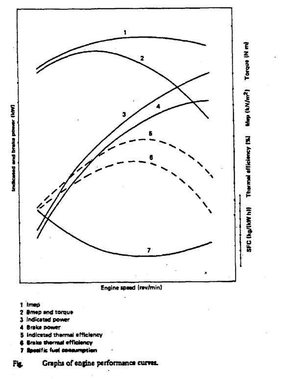
Specific fuel consumption represents the mass or volume of fuel an engine consumes per hour while it produces 1 kW of power. It is an indication of the engine’s thermal or heat efficiency and is one of the most important engine characteristics. Comparisons can be made between engines of widely different capacities and characteristics, providing similar fuel and test conditions are arranged for each test.
A mirror reflection of the specific consumption curve shows the shape of the engine’s thermal efficiency curve. The lowest point on the consumption curve becomes the highest point on the thermal efficiency curve.
If the specific fuel consumption (SFC) = FC/ P = (kg/h)/kW = kg/(kW h)
Brake specific fuel consumption (BSFC):
BSFC = (mass of fuel consumption/h) / engine brake power
Indicated specific fuel
consumption (ISFC)
ISFC=
(mass of fuel consumption/h) / engine indicated power
The minimum specific fuel consumption of gasoline engines are around 300 [g/(kW h)] and of diesel engines are around 240 [g/(kW h)].
For instance, typical gasoline engines will have an SFC of about 0.5 lb/(hp·h) or (0.3 kg/(kW·h) = 83 g/MJ), regardless of the design of any particular engine. Generally, SFC within a particular class of engine will decrease when the compression ratio is increased. Diesel engines have better SFCs than gasoline, largely because they have much higher compression ratios and therefore they can convert more of the heat produced into power.
* Motorists assess fuel consumption in terms of kilometer per liter (km/L), liter per 100 km (liter/100 km), mile per gallon (mpg)
Diesel efficiency:
The factors that increase the fuel economy of a diesel engine are its “super lean” air-fuel ratio, extremely high compression ratio, and the high heat value of fuel.
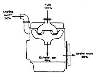
Thermal efficiency (hth)
The efficiency of an engine in converting the heat energy contained in the liquid fuel into mechanical energy is termed its thermal efficiency. A study of the results taken from heat balance tests shows clearly that internal combustion engines are inefficient at this conversion. Passenger car diesel engines have energy efficiency of up to 41% but more typically 30%, and petrol engines of up to 37.3%, but more typically 20%.

where:
CV is the calorific or heat value of 1 kg of the fuel (J/kg, kJ/kg or MJ/kg).

where
ρ is the relative density (kg/L) of the fuel.
BSFC is the brake specific fuel consumption.
bmep = imep hm
hth i = ![]()
The calorific value of a fuel (CV):
It is quantity of heat produced by its combustion at constant pressure and under “normal” conditions (i.e. 0o C and under a pressure of 1,013 mbar)
The combustion process generates water vapor and certain techniques may be used to recover the quantity of heat contained in this water vapor by condensing it.
The Higher Calorific Value (or Gross Calorific Value- GCV) suppose that the water of combustion is entirely condensed and that the heat contained in the water vapor is recovered.
The Lower Calorific Value (or Net Calorific Value- NCV) suppose that the products of combustion contains the water vapor and that the heat in the water vapor is not recovered.
|
Fuel |
Higher Calorific Value (Gross Calorific Value- GCV) |
|
|
kJ/kg |
|
Alcohol, 96% |
29,000 |
|
Diesel |
44,800 |
|
Ethanol |
29,700 |
|
Gasoline |
47,300 |
|
Hydrogen |
141,790 |
|
Methane |
55,530 |
|
|
kJ/m3 |
|
Butane C4 H10 |
133,000 |
|
Hydrogen |
13,000 |
|
Natural gas |
43,000 |
|
Methane C H4 |
39,820 |
|
Propane C3 H8 |
101,000 |
Engine performance curves:
Factors affect the engine torque and power:
Pre -ignition, detonation, retarded ignition, weak mixture, engine load, piston speed, ignition timing, camshaft advanced or crankshaft retarded, tappet clearances, variation of compression ratio, fuel pump injection timing, supercharging.

Power to weight ratio (single-and multi-cylinder engines):
The engine power varies as the square of the bore (piston area) but the mass varies as the cube of the bore (that is with the volume used). Increasing power by using a large cylinder therefore results in a low power/weight ratio, where as increasing the number of cylinders maintains power to weight in the same proportion.