II

Engine Testing
1) Engine indicators
Engine indicators are instruments which record the pressure and volume of the gases within the engine cylinder on a diagram, and make possible the study of the entire cycle with alterations or modifications to the air/fuel ratio, ignition timing, speed and load characteristics being recorded.
The indicator diagrams:
(pressure-volume [ pV diagram]) & (pressure - crank-angle)
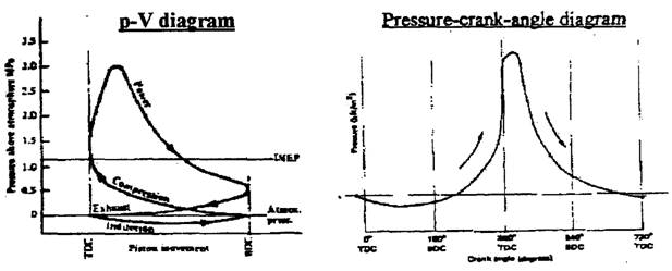
The driving force on the engine piston is a variable one and the mean value (imep) is used to determine the indicated power. The area of such a diagram represents to some scale the work done during one cycle of the engine pistons. The area may be found by the mid-ordinate method or by planometer. Some of the indicators are used to produce the pressure-volume diagrams and others are used to produce the pressure-crank-angle diagrams. Sparking plugs which have the dual role of igniting the charge and transmitting pressure pulses are used in certain research work.
2) The Morse Method
An engine connected to a absorption-type dynamometer with load weighing gear and tachometer will enable the indicated power (Pi) and mechanical efficiency (ηm) to be calculated within reasonable limits of accuracy, providing care is taken to maintain the exact rev/min and particular attention is paid to the torque arm setting and the reading of the load figures.
The test consists of measuring the total brake power (Pb) with all engine cylinders working normally under full throttle, and the cutting out each cylinder in turn. With spark ignition engines it is a simple matter to short each cylinder in turn, and various gadgets are produced for this purpose. With oil engines, using in-line fuel injection pumps, the raising of the fuel pump cam follower with a screwdriver or similar tool will cut off the fuel supply to that cylinder without having fuel oil leaking around the test area. This is the case if pipe unions are loosened to prevent injection. When a cylinder has been cut out, the remaining working cylinders have to overcome the frictional and pumping loses of the cut-out cylinder.
Consider a four cylinder four-stroke engine:
Let A = brake power Pb of 4 cylinders which equals 4 Pi - 4 Pf
(where Pi = indicated power and Pf = friction power)
and B = Pb of 3 cylinders which equals 3 Pi - 4 Pf
thus: case A - case B = 1 Pi, which is the indicated power of the cut-out cylinder.
When each cylinder’s indicated power is known and added together, the result gives the total indicated power for the engine under those speed and load conditions.
Worked example
A four-cylinder four-srtoke engine was Morse tested at 2000 rev/min. The data is tabulated below.
|
Cylinder cut-out |
Pb (kW) |
Measured |
|
None |
32.87 |
Pb |
|
No. 1 |
23.73 |
Pb- Pi (1) |
|
No.2 |
23.82 |
Pb- Pi (2) |
|
No. 3 |
23.35 |
Pb- Pi (3) |
|
No. 4 |
23.94 |
Pb- Pi (4) |
Pi (of the n th. Cylinder) = engine Pb(all cylinders) - engine Pb (No. n cutout)
Pi (1st cylinder) = Pi (1) = 32.87 – 23.73 = 9.14 kW
Pi (2nd cylinder) = Pi (2) = 32.87 – 23.82 = 9.05 kW
Pi (3rd cylinder) = Pi (3) = 32.87 – 23.35 = 9.52 kW
Pi (4th cylinder) = Pi (4) = 32.87 – 23.94 = 8.93 kW
The engine indicated power = Pi (1) + Pi (2) + Pi (3) + Pi (4)
Engine Pi = 9.13 + 9.05 + 9.52 + 8.93 = 36.64 kW
The friction power (Pf) = Pi - Pb = 36.64 – 32.87 = 3.77 kW
The mechanical efficiency (hm) = Pb/Pi = 32.87 / 36.64 = 89.71%
3) Heenan and Froude Hydraulic dynamometer
The brake power (Pb) of an engine is the useful power available at the crankshaft of the engine. It is measured by running the engine against some form of absorption brake, hence its name. For high-speed motor vehicle engines, the type of brake widely used is the Heenan and Froude hydraulic dynamometer. It consists essentially of a rotor running in a casing through which water flows steadily via the inlet and outlet pipes. The rotor is coupled to the engine output shaft, and the casing is freely mounted on bearings fitted to the trunnion brackets.
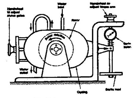
At the periphery of the rotor there is a series of semi-elliptical pockets, so that, when the rotor is driven by the engine, the water is flung Hydraulic dynamometer out of its pockets by centrifugal action ad transferred to the pockets in the casing. This results in a tendency to turn the casing with the rotor. The casing is prevented from rotating by the resistance of a spring and a static (or dead) load applied to the torque arm which projects from the casing. A hand wheel is provided on top of the balance frame to adjust the torque arm to a horizontal position; this is facilitated by a small pointer, as shown. The amount of load and, hence, the torque absorbed by the dynamometer can be varied by controlling the flow of water. This is usually done by operating another hand wheel which slides thin metal plates between the rotor and the casing pockets, thus, blanking-off a number of effective pockets.
As the length of the torque arm, together with the static load and spring balance reading, is known, the torque on the casing can be determined. This is balanced by the torque transmitted by the engine.
Then,
Torque (T) transmitted by engine
T = Effective load x Length of torque arm
i.e. T = W . R (N m)
where,
W = S + W1
S = spring balance reading (N)
W1 = static load (N)
R = length of torque arm (m)
If the engine is running at N rev/min, then:
Brake power Pb = 2π N W R/60 (W)
= 2π N T/60 (W)
It should be noted that since R is a fixed length for a given dynamometer, the terms (2 π R)/ 60 may be written:
(2 π R)/ 60 = 1/ K
The value of the constant K is usually stamped on the nameplate attached to the dynamometer.
Thus, the Pb formula for the dynamometer may be reduced to the simple form:
Pb=W N /K (W)
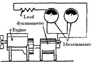
4) Motoring method
If an electrical swinging-field dynamometer is available the engine on test can be motored directly after the power curve readings have been recorded. The dynamometer motors the engine through the same rev/min range with ignition or fuel oil cut off (throttle wide open). Brake load readings are taken and frictional power (pumping + frictional losses) is obtained as follows:
Pi = Pb + Pf
ηm = Pb/Pi
The temperature of he engine’s pistons and cylinder walls, together with other working parts and also the engine oil, falls bellow that of normal working temperature during the motoring tests, and with the lack of exhaust gases, etc, the frictional and pumping losses are somewhat modified. It, however, the test is done quickly and smartly with good teamwork the results can be better than those produced by the Morse method. In the latter there is a torsional balance upset and the charge within their induction manifold has its flow modified together with the change in exhaust gas flow at the ports and manifold.
It is possible with such a dynamometer to evaluate the frictional and pumping losses of various engine parts by taking readings as parts have been dismantled.
Worked example:
An engine under mechanical efficiency test is connected to an electrical swinging- field dynamometer. The brake power reading was 24 k W at l500 rev/min. On motoring test at the same engine speed the power reading was 6.07 kW. Calculate the indicated power and the mechanical efficiency.
Pi = Pb + Pf = 24 + 6.07 = 30.07 (kW)
ηm = Pb / Pi
= 24/ 30.07 = 0.789 = 78.9%
https://en.wikipedia.org/wiki/Testing_and_performance_of_IC_engines
http://www.mh-aerotools.de/airfoils/engingeperformance.htm
http://3ln.org/articles/horsepower-vs-torque