Shafts
Introduction:
The term ‘shaft’ usually refers to a component of circular cross-section that rotates and transmits power from a driving device, such as a motor or engine, through a machine, or stationary.
Shafts can carry gears, pulleys, and sprockets to transmit rotary motion and power via matting gears, belts, and chains. Alternatively, a shaft may simply connect to another via a coupling. Shafts also can carry flywheels.
The word “shaft” covers numerous variations, such as axles and spindles. An axle is a shaft, either stationary or rotating not subjected to a torsion load. A short rotating shaft is often called a spindle.
|
|
|
|
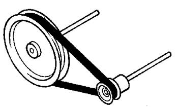
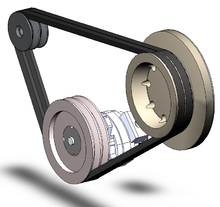
Pulley and belt system |
|
|
|
|
|
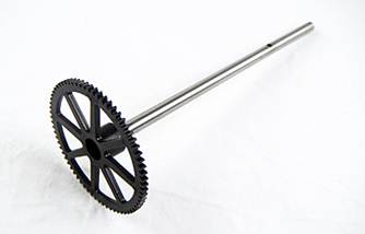
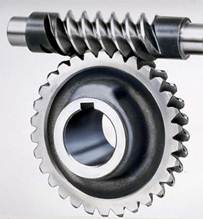
Gear system |
|
|
|
|
|
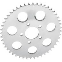
Sprocket and chains system |
|
Shaft
Design and Analysis
A shaft is the component of a mechanical device that transmits rotational
motion and power. It is integral to any mechanical system in which power is
transmitted from a prime mover, such as an electric motor or an engine, to
other rotating parts of the system. There are many examples of mechanical
systems incorporating rotating elements that transmit power: gear-type speed
reducers, belt or chain drives, conveyors, pumps, fans, agitators, household
appliances, lawn maintenance equipment, parts of a car, power tools, machines
around an office or workplace and many types of automation equipment.
Visualize the forces, torques, and bending moments that are created in the
shaft during operation. In the process of transmitting power at a given
rotational speed, the shaft is inherently subjected to a torsional moment, or
torque. Thus, torsional shear stress is developed in the shaft. Also, a shaft
usually carries power-transmitting components, such as gears, belt sheaves, or
chain sprockets, which exert forces on the shaft in the transverse direction
(perpendicular to its axis). These transverse forces cause bending moments to
be developed in the shaft, requiring analysis of the stress due to bending. In
fact, most shafts must be analyzed for combined stress.
Because of the simultaneous occurrence of torsional shear stresses and normal
stresses due to bending, the stress analysis of a shaft virtually always
involves the use of a combined stress approach. The recommended approach for
shaft design and analysis is the distortion energy theory of failure. Vertical
shear stresses and direct normal stresses due to axial loads also occur at
times, but they typically have such a small effect that they can be neglected.
On very short shafts or on portions of shafts where no bending or torsion
occurs, such stresses may be dominant.
Shaft geometry:
Shafts typically consist of series of stepped diameters accommodating bearing mounts and providing shoulders for locating devices, such as gears, sprockets and pulleys to butt up against and keys are often used to prevent rotation, relative to the shaft, of these ‘added’ components.
General Considerations:
1. To minimize both deflections and stresses, the shaft length should be kept as short as possible and overhangs minimized.
2. A cantilever beam will have a larger deflection than a simply supported (straddle mounted) one for the same length, load, and cross section, so straddle mounting should be used unless a cantilever shaft is dictated by design constraints.
3. A hollow shaft has a better stiffness/mass ratio (specific stiffness) and higher natural frequencies than a comparably stiff or strong solid shaft, but will be more expensive and larger in diameter.
4. Try to locate stress-raisers away from regions of large bending moment if possible and minimize their effects with generous radii and relief.
5. General low carbon steel is just as good as higher strength steels (since deflection is typical the design limiting issue).
6. Deflections at gears carried on the shaft should not exceed about 0.005 inches (0.13 mm) and the relative slope between the gears axes should be less than about 0.03 degrees.
7. Deflection of the journal section of the shaft across a plain bearing should be small in comparison of the oil film thickness (slope of the shaft axes across the plain bearing should be less than the oil film thickness).
8. Whenever possible, the power-transmission elements, such as gears or pulleys, should be located close to the supporting bearings. This reduces the bending moment and hence the deflection and bending stress.
Shaft design considerations include:
1- Size and spacing of components (as on a general assembly drawing), tolerances.
2- Material selection, material treatments.
3- Deflection and rigidity.
- Bending deflection
- Torsional deflection
- Slope at bearing
- Shear deflection
4- Stress and strength
- Static strength
- Fatigue
- Reliability
5- Frequency response.
6- Manufacturing constraints.
7- Shaft Design Guidelines
• Keep shafts short and minimize cantilever designs.
• Hollow shafts have better stiffness/mass ratios, but are more expensive.
• Configure shaft geometry to reduce stress concentrations.
• Remember that gears can produce radial, tangential, and axial loads.
• Be aware of maximum shaft deflection requirements of bearings.
• Shaft natural frequency should be as high as practical.
Shaft loads:
Shafts can be subjected to a variety of combination of axial, bending and torsional loads which may fluctuate or vary with time. Typically a rotating shaft transmitting power is subjected to a constant torque together with a completely reversed bending load, producing a mean torsional stress and an alternating bending stresses, respectively.
Shafts must be designed so that deflections are within acceptable levels.
Shafts should be designed to avoid operation at, or near, critical speeds. This is usually achieved by the provision of sufficient lateral rigidity so that the lowest critical speed is significantly above the range of operation.
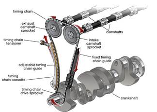
If torsional fluctuations are present (engine crankshafts, cam-shafts, compressors) the torsional natural frequencies of the shaft must be significantly defferent to the torsional input frequency. This can be achieved by providing sufficient torsional stiffness so that the shaft’s lowest natural frequency is much higher than the highest torsional input frequency.
Shaft-hub connection
Power transmitting components such as gears, pulleys and sprockets need to be mounted on shafts securely and located axially with respect to mating components. In addition, a method of transmitting torque between the shaft and the component must be supplied. The portion of the component in contact with the shaft is called the hub and can be attached to, or driven by, the shaft keys, pins, setscrews, press and shrink fits, splines and taper bushes.
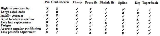
Table 1 identifies the merits of various connection methods. Alternatively the components can be formed as an integral part of a shaft as, for example, the cam on as automotive cam-shaft.
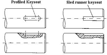
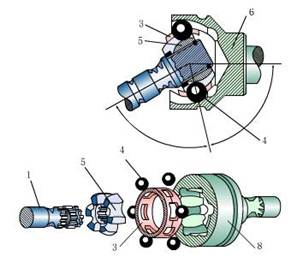
Figure 1 illustrates the practical implementation of several shaft hub connection methods. Gears, for example, can be gripped axially between a shoulder on a shaft and a spacer with the torque transmitted through a key.
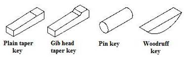
Various configurations lf keys exist including square, flat and round keys as shown in Figure 2. The grooves in the shaft and hub into which the key fits are called keyways or keyseats. A simpler and less expensive method for transmitting light loads is to use pins, and various types are illustrated in Figures 2 and 3. One of the simplest hub-shaft attachments is to use an interference fit, where the hub bore is lightly smaller than the shaft diameter. Assembly is achieved by press fitting, or thermal expansion of the outer ring by heating and thermal contraction of inner by use of liquid nitrogen.
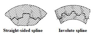
Mating spines, as shown in Figure 4, comprise teeth cut into both the shaft and the hub and provide one of the strongest methods of transmitting torque. Both splines and keys can be designed to allow axial sliding along the shaft.
Table 1 Merits of various shaft-hub
connections
|
|
|
|
|
|
|
Alternative methods of shaft-hub connections |
Shaft-shaft connection couplings:
In order to transmit power form one shaft to another, a coupling or clutch can be used.
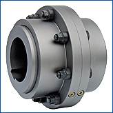
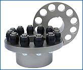
There are two general types of coupling, rigid and flexible.
Rigid couplings are designed to connect two shafts together so that no relative motion occurs between them. Rigid coupling are suitable where precise alignment of two shafts is required. If significant radial or axial misalignment occurs high stresses may result which can lead to early failure.
|
|
|
|
Rigid coupling |
|
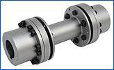
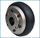
Flexible couplings are designed to transmit torque, whilst permitting some axial, radial and angular misalignment.
|
|
|
|
Flexible coupling |
|
Each coupling is designed to transmit a given limiting torque. Generally flexible couplings are able to tolerate up to ± 3o of angular misalignment and up to 0.75 mm parallel misalignment depending on their design. If more misalignment is required a universal joint can be used.
|
|
|
|
Universal joint (U joint) |
|
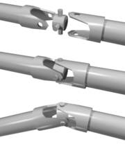
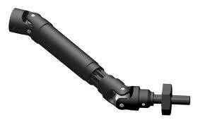
A universal joint, universal coupling, U joint, Cardan joint, Hardy-Spicer joint, or Hooke's joint is a joint or coupling in a rigid rod that allows the rod to 'bend' in any direction, and is commonly used in shafts that transmit rotary motion. It consists of a pair of hinges located close together, oriented at 90° to each other, connected by a cross shaft.
|
|
|
|
Constant-velocity joint (CV joint) |
|
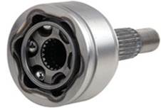
Constant-velocity joints (CV joints) allow a rotating shaft to transmit power through a variable angle, at constant rotational speed, without an appreciable increase in friction or play. They are mainly used in front wheel drive and all wheel drive cars. Rear wheel drive cars with independent rear suspension typically use CV joints at the ends of the rear axle halfshafts, and increasingly use them on the propshafts. Audi Quattros use them for all four half-axles and on the front-to-rear driveshaft (propeller shaft) as well, for a total of ten CV joints.
|
|
|
|
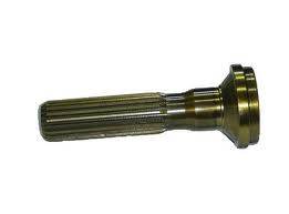
Splines shafts |
|
|
|
|
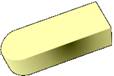
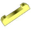
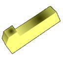
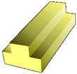
Keys for torque transmission and component location. |
|
|
|
|
|
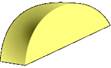
Woodruff Key |
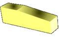
Plain Taper Key |
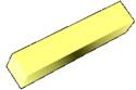
2 Round End Key |
|
|
|
|
|
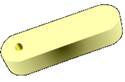
Round End Drilled Key |
Cut Length Keysteel |
1 Round End Key |
|
|
|
|
|
Double Gib Head Key |
Gib Head Keys |
Stepped Key |

Shafts may be subjected to bending, tension, compression, or torsional loads, acting singly or in combination with one another. When they are combined, one may expect to find both static and fatigue strength to be important design considerations, since a single shaft may be subjected to static stresses, completely reversed stresses, ad repeated stresses, all acting at the same time.
|
|
