Helical (Coil) Springs
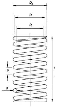
The figure shows a helical coil spring with ends adapted to support a compressive load. The notation applied are:
|
P = axial load, N D = mean diameter of coil, mm = (Do + Di) / 2 d = diameter of wire, mm = (Do – Di) / 2 p = pitch of coils, mm δ = deflection of spring, mm n = number of active coils C = spring index = D/d = (Do-d)/d = (4 : 12); less than 4; it is difficult to manufacture, more than 12; it is likely to buckle. G = torsional modulus of elasticity, N/mm2 τs = shearing stress, N/mm2 |
|
Stresses on coil spring (t):
The coil spring wire is subjected to the following stresses:
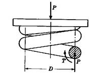
a- Torsional stress due to the load P
b- Direct shear stress due to load P
c- Torsional stress due to wire curvature
Torsional stress due to load P:
![]()
In order to include the effects of both direct shear and wire curvature, a stress factor (Kw) had been determined by the use of approximate analytical methods developed by A. M. Wahl:
![]()
which may be used in the above equation to determine the maximum shearing stress in the wire as follows:
![]()
Various lengths associated with a spring:
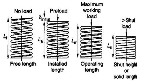
Lf = Free length
La = Installed length
Lm = Operating length
Ls = Shut height or Solid length
· Compression springs in which the free length is more than four times the mean diameter of the coils may fail by sidewise buckling.
Spring deflection (d):
![]()
Spring rate (stiffness) (k):
![]()
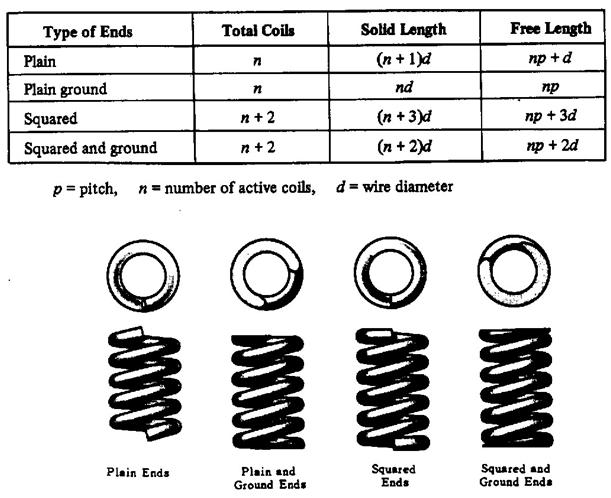
Spring ends conditions:
Helical springs ends may be either plain, plain ground, squared, or squared and ground as shown in the figure below. This results in a decrease of the number of active coils and affects the free length and solid length of the spring as shown below.
p=(D/3 : D/4), n= ( 3: 15)
Finding spring stress and deflection:
a- Using the above equations of tmax , and d.
b- Using the nomogram
c- Using the Excel program given
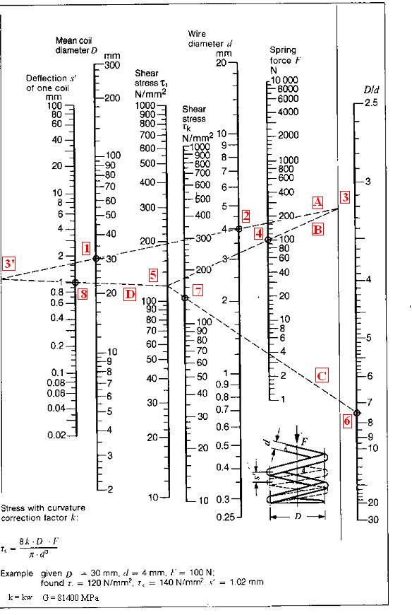
Explanation of the nomogram:
The nomogram applies to cylindrical helical extension and compression springs made of round steel wire (shear modulus G=81,400 N/mm2). In the case of materials with a different shear modulus G’ spring deflection must be multiplied by G/G’.
The nomogram indicates the deflection s’ of one coil. Total deflection s (d) is obtained by multiplying (s’) by the number of active coils n:
s (d) = n . s’.
Example:
Find the stress and the deflection of a spring with the following dimensions:
D = 30 mm
d = 4 mm
F = P = 100 N
Solution steps:
1- enter the value of D (point 1), and d (point 2) into the nomogram
2- connect point 1, 2 with the line A and extend the line to points 3 and 3’ on either end.
3- enter the value of F (point 4) into the nomogram
4- connect point 3 to the value of the force F (point 4) with line B, extend the line B to point (5)
5- calculate the value of C and enter its value into the nomogram (point 6)
6- connect point 6 and 5 by line C to obtain point (7)
7- connect point 5 to point 3’ to obtain point (8)
Solution:
- point 5 represents the value of tt (MPa)
- point 7 represents the value of tmax (MPa)
- point 8 represents the value of d’ = d/n (mm)
- enter the values of d, D, P, n, G.
The program will give you the values of C, Kw, tt (Tau”) , tmax (Tau), d/n (Delta”), d (Delta), and K