Keys and Splines
A key is a component inserted between the shaft and the hub of a pulley, wheel, etc., to prevent relative rotation but allow sliding movement along the shaft, if required.
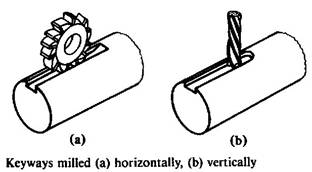
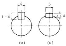
The recess machined in a shaft or hub to accommodate the key is called a keyway. Keyways can be milled horizontally or vertically, as shown in the figure below. Keys are made of steel, in order to withstand the considerable shear and compressive stresses caused by the torque transmit.
|
|
There are two basic types of key:
(a) Saddle keys, which are sunk into the hub only. These keys are suitable only for light duty, since they rely on a friction drive alone.
(b) Sunk keys, which are sunk into the shaft and into the hub for half their thickness in each. These keys are suitable for heavy duty, since they rely on positive drive.
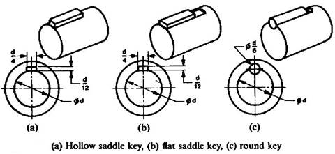
Hollow saddle keys are used for very light duty, fig.(a) below.
Flat saddle keys are used for light duty, fig. (b) below.
Round keys are used for medium duty, fig. (c) below.
|
|
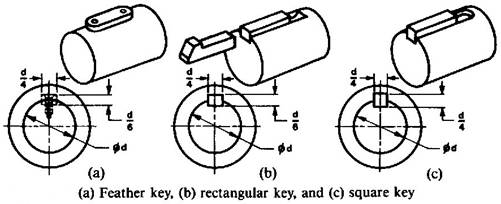
Feather key is used when the hub is required to slide along the shaft. It is lightly fitted or secured by means of screws in the shaft keyway, and is made to slide in the hub keyway, fig. (a) below.
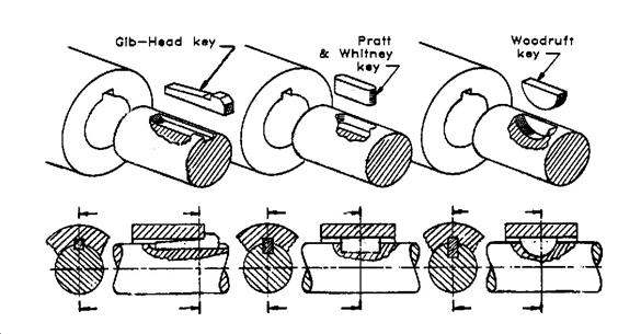
Rectangular and square keys can be parallel or tapered with a basic taper of 1 in 100 to prevent sliding. These keys are used for heavy-duty applications. It is advised to use square keys for assembly-drawing solutions. Gib heads are sometimes provided on taper keys to facilitate their withdrawal, fig. (b) and fig. (c) below.
|
|
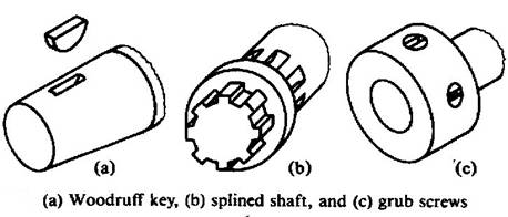
Woodruff key is an almost semi-circular disc which fits into a circular keyway in the shaft. The top art of the key stands proud of the shaft and fits into the keyway in the parallel or tapered hub. As the key can rotate in the keyway, it can fit any tapered hole in the hub, fig. (a) below.
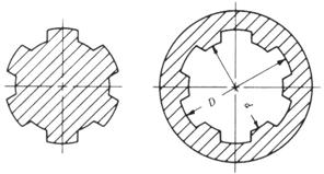
A splined shaft is used when the hub is required to slide along the shaft. These shafts are used mostly for sliding-gear applications. The splines are usually milled and the splined holes broached, fig (b) below.
Square-head set screws and grub screws are also used for low-torque applications, fig. (c) below.
If the torque to be transmitted is too great for one grubscrew or key, two may used set at 90o to 120o around the shaft, but never at 180o.
|
|
 DESIGN OF SQUARE AND FLAT KEYS
 may be based on the shear and compressive
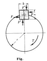
stresses induced in the key as a result of the torque being transmitted. The
forces acting on the key are shown in the figure. The forces F’
act as a resisting couple to prevent the key from tending to roll in the fitted
keyway. The exact location of the force F is not known and it is
convenient to assume that it acts tangent to the surface of the shaft. This
force produces both shear and compression stresses in the key.
may be based on the shear and compressive
stresses induced in the key as a result of the torque being transmitted. The
forces acting on the key are shown in the figure. The forces F’
act as a resisting couple to prevent the key from tending to roll in the fitted
keyway. The exact location of the force F is not known and it is
convenient to assume that it acts tangent to the surface of the shaft. This
force produces both shear and compression stresses in the key.
Resistance to the shaft torque T may then be approximated by T = Fr, where r is the radius of the shaft. The shearing stress t in the key is
![]()
where L is the length of the key.
The shaft torque that the key can sustain from the standpoint of shear Ts is
![]()
The compressive stress σc in the key is
![]()
The shaft torque that the key can sustain from standpoint of compression is
![]()
* Square key can sustain the same shaft torque form the stand point of shear as it can from the stand point of compression. This is can be proved by equating the two torque equations and making use of the approximate relation σc = 2t, for ductile steels. On this same basis, flat keys which are wider than they are deep will fill in compression, and feather keys which are deeper than they are wide will file in shear.
* The width of the square and the flat key is usually one fourth the diameter of the shaft [b = (1/4) D].
SPLINES CONNECTION are used to permit relative axial motion the shaft and hub of the connected member. The splines are keys made integral with the shaft and usually consist of four, six, or ten in number. When there is relative axial motion in a splined connection, the side pressure on the splines should be limited to about 7 MPa. The torque capacity of a splined connection is
![]()
where
p = permissible pressure on the splines < 7 MPa
 A = total load area of
splines, m2 = ½ (D-d) (L) (n), m2
A = total load area of
splines, m2 = ½ (D-d) (L) (n), m2
D= shaft diameter, m
d = D – twice the depth of the splines
L= length of hub, m
n = number of splines
rm = mean radius, m
For splines in shear, the force P acting on a spline at the mean spline diameter Dm is given by
![]()
and 
where
b = spline width, n = number of splines, L = spline length
For splines in bending, given bending moment