How to Find Your Car’s Gearbox and Final Drive Ratios and Efficiencies?
The internal combustion engine used in a modern vehicle will only operate over a limited effective speed range, e.g. 1500-5000 rev/min, and in this range will produce a comparatively low torque (turning effort). When the speed drops below the lower limit, or if the load is too great, the engine will stall and the vehicle will come to rest.
The transmission (gearbox) or transaxle is a vital link in the power train of any vehicle. The propose of the transmission or transaxle is to use gears of various sizes to give the engine a mechanical advantage over the driving wheels. Gears in the transmission or transaxle housing alter the torque and speed of this power input before passing it on to the other components in the power train. Without the mechanical advantage the gearing provides, an engine can generate only limited torque at low speeds. Without sufficient torque, moving a vehicle from a standing start would be impossible. Also, the transmission or transaxle provides the gearing needed to reverse direction so the vehicle can be driven backward.
The necessity for a gearbox:
Power from a petrol or diesel reciprocating engine transfers its power in the
form of torque and angular speed to the propelling wheels of the vehicle to
produce motion. The object of the gearbox is to enable the engine’s turning
effect and its rotational speed output to be adjusted by choosing a range of
under- and overdriving gear ratios so that the vehicle responds to the driver’s
requirements within the limits of the various road conditions.
Al low engine speed, a reciprocating-piston engine does not develop sufficient turning effort or torque to propel a vehicle forward from standstill. Even the greater torque produced at higher engine speed would be insufficient to accelerate the vehicle at a reasonable rate. The gearbox provides a way of varying the engine’s output torque and speed to match the vehicle’s speed and load.
- The high gear ratio means the lower is the reduction between the engine and the road wheels. Conversely the lower the gear ratio means the greater is the reduction between the engine and road wheels. The top gearbox ratio is 1:1 when the gearbox input shaft connects directly with the gearbox output shaft; in this case, it calls direct drive.
Example:
- Most gearboxes have an over drive shift. The overdrive consists of an electrically or hydraulically operated epicyclic gear train bolted behind the transmission unit. It can either couple the input driveshaft directly to the output shaft (or propeller shaft) (1:1), or increase the output speed so that it turns faster than the input shaft (1:1 + n). Thus the output shaft may be "overdriven" relative to the input shaft. With the use of front-wheel drive layouts, the gearbox and final drive are combined into a single transaxle. There is no longer a drive shaft between them and so the notion of "direct drive" is simply inapplicable. Although "overdrive" is still referred to, this is now mostly a marketing term to refer to any extra-high ratio for efficient cruising, whether it is achieved through the gearbox ratios, or by an unusually high final drive.
|
|
|||||
|
Shift |
1st |
2nd |
3rd |
4th * |
5th ** |
|
Transmission ratios |
3.81 |
2.71 |
1.37 |
1.00 |
0.81 |
|
|
|||||
* Top gear, direct drive (DD)
** Over drive (OD)
Transmission Efficiency η:
There will be power (energy) losses when using gear system to transmit the torque, which is due to many factors like: friction between gears teeth, the motion of lubricant in the gearbox, etc…
Output power = input power × η
Output power = input power – loss power
Using the above equation we can obtain the gearbox efficiency at each shift.
η = output power/input power = (input power – loss power)/input power
= 1- (loss power/input power)
* The transmission efficiency decreases with the increase in reduction ratio (lower gear).
Types of gearbox (transmission):
- Manual transmission (using wheel gears or compound gear train)
Manual transmissions often feature a driver-operated
clutch and a movable gear stick. Most automobile manual transmissions allow the
driver to select any forward gear ratio ("gear") at any time, but
some, such as those commonly mounted on motorcycles and some types of racing
cars, only allow the driver to select the next-higher or next-lower gear. This
type of transmission is sometimes called a sequential manual transmission.
Sequential transmissions are commonly used in auto racing for their ability to
make quick shifts.
http://thecartech.com/subjects/auto_eng/Auto_eng_3.htm
http://www.thecartech.com/subjects/auto_eng/Types_of_Trnasmission.htm
- Automatic transmission (using planetary gears)
It is one type of motor vehicle transmission that can automatically change gear ratios as the vehicle moves, freeing the driver from having to shift gears manually. Most automatic transmissions have a defined set of gear ranges, often with a parking pawl feature that locks the output shaft of the transmission.
http://thecartech.com/subjects/auto_eng/Auto_eng_4.htm
- Continuously variable transmissions (CVTs)
They are another transmission technology that's available in some cars. Instead
of having fixed gear ratios like a conventional manual or automatic, CVTs
constantly adjust to the current driving conditions. Since there are no gear
"steps" to shift between, CVTs often operate more smoothly than other
technologies.
Terminology and definitions:
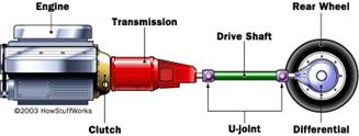
Transmission: In British English, the term transmission refers to the whole drive (power) train, including clutch, gearbox, prop shaft (for rear-wheel drive), differential, and final drive shafts. In American English, however, a gearbox is any device that converts speed and torque; whereas a transmission is a type of gearbox that can be “shifted” to dynamically change the speed-torque ratio such as in a vehicle.
Gearbox/Transmission (reduction speed device): It refers simply to the gearbox that uses gears and gear trains to provide speed and torque conversions from a rotating power source to another device. In motor vehicles, the transmission generally is connected to the engine crankshaft via a flywheel and/or clutch and/or fluid coupling. The output of the transmission is transmitted via driveshaft to one or more differentials, which in turn, drive the wheels.
Differential: It may also provide gear reduction (final reduction ratio); its primary purpose is to permit the wheels at either end of an axle to rotate at different speeds (essential to avoid wheel slippage on turns) as it changes the direction of rotation.
Transaxle: It is a major mechanical component in the car that combines the functionality of the transmission, the differential and associated components of the driven axle into one integrated assembly. Transaxles are near universal in all automobile configurations that have the engine placed at the same end of the car as the driven wheels: (the front-engine, front-wheel drive) layout, (rear-engine, rear-wheel drive) layout and (rear mid-engine, rear-wheel drive) layout arrangements.
http://thecartech.com/subjects/auto_eng/transmission_system_2.aspx
Torque (N m):
Engine torque; Te, Gearbox output torque Tg;
wheel torque; Tw
Speed (rpm): Ne (rpm) = engine speed, Ng = gearbox
output speed, Nw = wheel speed
Reduction ratios: gearbox reduction ratio; ig = (1: ig)
(ig1 = 1st gear reduction ratio, ….) - final drive
ratio; if = (1: if) - total power train reduction
ration; it = (ig × if)
Efficiency (%): gearbox (transmission) efficiency; ηg
= (ηg1=1st gear efficiency, ηg2=2nd
gear efficiency, …. ) - final drive efficiency - ηf (%);total
drive efficiency; ηt = (ηg × ηf)
Number of gear teeth: n, (nA = number of teeth in gear A, ….)
|
|
|
|
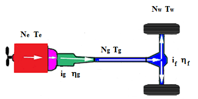
The gear ratio (ig) of a gear train is the ratio of the angular velocity of the input gear Ne (engine side) to the angular velocity of the output gear Ng (propeller shaft and differential side), also known as the speed ratio of the gear train. Hence, ig = Ne/Ng.
The final drive ratio (if) of a differential unit of drive shaft is the ratio of the input angular velocity Ng (propeller shaft side) to the unit to the output velocity of the unit Nw (drive axle and drive wheels side). Hence, if = Ng/Nw.
The total drive ratio (it) of a vehicle is the ratio between the engine angular velocity Ne to the drive axle and driving wheel angular velocity Nw. Hence, it = ig × if = (Ne/Ng) × (Ng/Nw) = Ne/Nw.
Method of finding the gearbox ratios:
a) From the car manual.
b) The
gear ratios can be calculated:
Directly from the number of teeth of the various gears that engage to form the
gear train. The torque ratio of the gear train, also known as its mechanical
advantage, is defined by the gear ratio.
c) Obtaining the reduction rations and efficiencies by carrying on experiments.
b) The gearbox and the differential are out of car and uncover:
b-1) Finding the gearbox reduction ratios (from number of gears teethes):
|
|
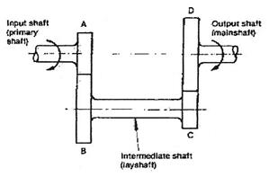
ig = (nD/nC) × (nB/nA) = (nD×nB) /(nC×nA) = (the multiplication of driven gears teeth numbers) divided by (the multiplication of driving gears teeth numbers), for the manual gear reduction shift gear combination.
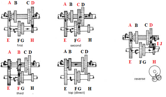
Example: Gearbox reduction ratios ig
|
|
|
First: ig1 = (nD × nE) / (nH × nA), Second: ig2 = (nC × nE) / (nG × nA), Reverse: igR = (nD × nJ × nE) / (nI × nH × nA( Third: ig3 = (nB × nE) / (nF × nA), Top (direct): i4 = 1.00,
|
b-2) Finding the final drive ratio(from number of gears teethes):
|
|
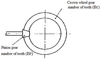
if = nC/nP
where:
if = final drive ratio
nc = crown wheel gear number of teeth
np = pinion gear number of teeth
c) Obtaining the reduction ratios and efficiencies of the gearbox and final drive experimentally:
Method (I) (the units are outside of the car):
(A) Finding the gearbox (gear ratios (ig..) and shifts efficiency (ηg...) Torque Balance:
|
|
The gearbox reduction ratios
can be found by experiment. Brief details are given below:
Fix a pulley on the input shaft and another one on the output shaft. Place a
chalk marks on the input and output pulley. Count the number of revolutions on
the input pulley needed to complete one revolution of output pulley. Repeat for
each gear ratio.
ig = revolutions of input pulley / one
revolution of output pulley
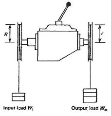
The shift efficiencies can be found by the following experiment:
Put a rope over each pulley and
i) Balance the input and output weights attached to the ropes (no
motion);
ηg = output torque / (input torque × ig)
= (wo × r) / (wi × R × ig)
Repeat the procedure for each gear shift to get ig1, ig2, ….. and ηg1, ηg2, …..
ii)
Using the work approach;
Carry on the same last experiment with pulleys of same diameters. With the
required gear shift selected, attach weights on the both the ropes of input (wi)
and output pulleys (wo). Let the pulleys to rotate under the loads,
measure the distances the input load (Li) and output load (Lo)
moves from rest for a short period of time.
Input work = Output work + Friction work
Gearbox efficiency at that shift = Output work/Input work = Wout/ Win
= (wo × Lo)/(wi × Li)
Repeat the procedure for all shifts
(B) Finding the final drive reduction ratio (if) and efficiency (ηf):
|
|
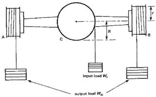
Measure the number of (revolution of input pulley C) and the number (revolutions of output pulleys A and B), then:
if = (number of revolutions of C) /(number of revolutions of [A+B]/2)
ηf = (output torque) / (input torque × if)
= (wo × r) / (wi × R × if)
Method (II), (the units are installed in the car- for manual transmission):
A simple experiment may be carried out to determine a vehicle final drive ratio and the gearbox ratios. If a starting handle is not available, a spanner may be used on the nut fitted at the nose of the crankshaft and fan pulley.
Procedure:
1- In case of rear wheel drive,
chock the front wheels and jack up one rear wheel.
In case of front wheel drive, chock the rear wheels and jack up one
front wheel.
Mark the jacked wheel’s tire and floor surface.
2- Select direct drive, (ig = 1). Rotate engine crankshaft until rear wheel had made exactly two revolutions. Note revolutions given to crankshaft.
Final drive ratio (if) = number of turns of crankshaft
3- Select and engage first gear and repeat above procedure (2) and again note exact revolutions of crankshaft.
Since the overall (total) reduction ratio it = ig × if therefore:
1st gear ratio ig1
= (number of crankshaft revolution per two crankshaft rev)/ (final drive ratio if)
4- Repeat the procedure for the other gears.
Note: When one wheel is raised off the road surface, and a standard type differential is fitted, the raised wheel will make double the normal number of revolutions.