Universal Joints
A universal joint
is a mechanical connection between two shafts with interconnecting axes. It
provides positive drive whilst allowing angular movement of one or both shafts.
Hooke’s joint:
The Hooke’s type of joint or cross arrangement is
widely used, and consists of a four-legged spider or cross fitting into Y-shaped
yokes on each shaft, needle rollers normally being used to reduce friction.
Speed variation of
a Hooke-type coupling:
These joints do not
transmit the drive at uniform speed when deflected. During each revolution the
driven shat is subject to two accelerations and two decelerations whose values
depend upon the angle of deflection — usually limited to 20°.
When an intermediate
shaft, e.g. a propeller shaft, has Hook’s joints at each end, provided the yokes
and the angles of the deflection at each are equal, the cyclic variation of the
intermediate shaft will be cancelled out by the second joint. The speed
fluctuation of the intermediate shaft remains, and this has resulted in the
replacement of the Hook’s joints by constant-velocity joints in many
applications.
Double, back-to-bake, Hooke’s joints have been used as constant-velocity joints,
but are now replaced by more compact devices.
Constant-velocity joints:
One principle
for constant velocity (CV) depends upon the engagement between the two shafts
place in the plane bisecting the angle between them. In addition to providing
constant velocity these joints will operate at approximately twice the angle of
divergence (40-45°) of a Hooke’s joint, and are particularly used for the
outboard couplings on front-wheel drive.
The Propeller Shaft
The propeller
shaft connects the gearbox to a live rear axle or a sprung rear drive unit for
the front engine RWD vehicle. It revolves at engine speed in direct drive, and
accurate dynamic balance is essential to prevent vibration.
The critical
whirling speed where resonant vibration will occur is inversely proportional to
the square of the length. For example, if the maximum speed for a 1 m shaft is
5500 rev/mm, which for a 1.25 m shaft of the same type is only 3500 rev/mm.
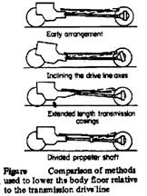
In order to
obviate vibration and noise the shaft length may be reduced by a rearward
extension on the gearbox or a forward extension on the rear drive unit.
Alternatively a divided propeller shaft is often used. The propeller shaft is
normally tubular in section and is made in a one- or two-piece construction.
During manufacture, steel shafts are balanced and during this operation small
patches, are spot-welded on the ‘light parts’ of the tube to correct the
imbalance.
Some form of
‘sliding’ or ‘telescopic’ joint is required in the propeller shaft assembly, so
that it can accommodate itself to small variation in effective length of the
drive line.
Transmission
tunnel height:
|
There are many
attempts to lower the car height, which in turn called for some lowering of
the body floor line. To provide the lowest possible transmission tunnel
height, thereby increasing rear seat foot room.
* The
propeller shaft either made of steel or composite material. The composite
propeller shaft has the advantage of less weight (50% reduction), high
internal shock absorption, and corrosion resistance.
|
|
Drive shafts
The drive shafts
connect to independently sprung front or rear road wheels. Being on the output
side of the final drive unit, they operate with that ratio of torque increase
and speed reduction compared with a propeller shaft.
In most cases
the shafts are of equal length and typically of 20-25 mm diameter nickel-
chromium steel. With a transversely mounted engine-transaxle unit,
unequal-length shafts may be required. The longer shaft can be partly of
larger-diameter tubular construction to equalize the torsional rigidity and
vibration characteristic with the shorter solid shaft.
The final drive and differential
The function
of final drive gears:
Final drive
gears are incorporated in vehicle driving axles for the following reasons:
·
To provide a
right-angle drive from either the propeller shaft, or the gearbox layshaft, to
the driven wheels.
• To permit an
additional and constant gear reduction in the transmission system. These
functions can be performed by bevel or worm gears.
The
final drive
The duty of the
final drive gears is to gear down the speed to suit the road wheels and redirect
the line of drive. A crown wheel and pinion bevel gear having a gear ratio of
about 4:1 is commonly used on cars but a lower ratio, e.g. 6:1 is necessary to
suit the large road wheels used on commercial vehicles;
v =
ωw
rw = [(2
π Ne/60) / (ig
if)] rw, TE
= Te
ηt
ig if / rw
Types of
bevel gear:
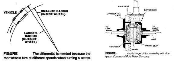
The hypoid gear
is in common use today
due mainly to the fact that the
offset pinion allows the propeller shaft to be set below, (for cars) or above,
(for commercial vehicles) the crown wheel centre. This gives either a reduction
in the/propeller shaft tunnel, which causes a bump in the vehicle floor, or in
the case of a commercial vehicle a reduction in the angle through which the
universal joint has to operate.
Worm and
wheel:
Today this
expensive form of drive is rarely used as a final drive on light vehicles, but
it is still used on heavy vehicles. Various arrangements, as shown in the figure
can be used to give a very quiet and long-lasting gear, but efficiency is not as
good as with the bevel (94 per cent against 98 per cent).
The back axle ratio
(final drive ratio) (if):
With the actual
gears he number of teeth on the crown wheel (the large cone) divided by the
number of teeth on the bevel pinion (the small cone) gives the ‘axle ratio’.
Also the gear ratio of a worm and wheel is given by dividing the number of teeth
on wheel by the number of starts on worm.
It should be
noted that a ‘high ratio’ axle refers in fact to one with a low numerical ratio.
For example, a final drive with an axle ratio of 4.10:1 is a ‘high ratio’ axle
as compared to one providing 4.56:1 ratio. In this connection, it will be
observed that the axle ration appears to be somewhat ‘fussy’ figure, such as
those just quoted. This is because the axle designer prefers to use an odd
number of teeth on the pinion so that each tooth on the crown wheel engages
every tooth on the pinion in regular succession.
Differentials
with a low (numerically high) gear ratio allow for fast acceleration and good
pulling power. Differential with high gear ratios allow the engine to run slower
at any given speed, resulting in better fuel conservation.
Special
transmission units:
a) Two speed axle;
this is a convenient method of providing a large number of gear ratios and
retaining a light gearbox. The torque applied to the final drive unit is also
moderate as the extra reduction and the increased torque are mad after the crown
wheel and pinion
Tw
(1st speed) = Te ig
ηt
i1, Tw
(2nd speed) = Te ig
ηt i2
where: i1,
i2
are the 1st and 2nd axle speeds respectively, and ηt
is the transmission efficiency.
b) Double reduction
axle; two reductions within the same unit
Tw
= Te ig
ηt
if = Te
ig
ηt
ia
ib
where: ia,
ib are the 1st and 2nd
reductions respectively.
c) Hub reduction;
a reduction made at the wheel hub reduces the stresses which would be applied to
the final drive unit having a large reduction ration. Fore example if a 2:1 hub
reduction is made this halves the torque to be transmitted to the axle shafts,
differential, crown wheel and pinion, propeller shaft and gearbox.
Tw = Te
ig ηt
if ih
where: if,
ih are the back axle
ratio and hub reduction respectively.
The differential
The differential
provides an equal torque to each half-shaft or drive shaft although they may be
rotating at different speeds. It therefore allows the outer road wheel to
revolve faster than the inner when cornering, whilst maintaining a positive
drive to both wheels.
Since no grater
torque can be transmitted to one road wheel than the other owing to the balance
action of the differential, if one road wheel is on a slippery surface where it
can revolve idly, no tractive force can be applied to the other wheel.
The limitation
of the differential -loss of drive if one wheel spines- can be eliminated by the
use of a differential lock, e.g. dog clutching one of the sun pinions to the
differential cage. Alternatively, a limited-slip differential (LSD) arrangement
with solid or viscous friction between the sun wheel and the differential cage
will apply some torque to the wheel having grip.
* The torque is
divided between the two wheels. The speed of inner and outer wheels can be
obtained from the following:
Let Nc
= rev/min of crown wheel or differential unit, Ni = rev/min of inner
wheel, and No = rev/min .of outer wheel. Then
Nc =
(Ni + No) /2
and
No
= (Nc x2) – Ni
or Ni = (Nc
x 2) - No
Rear axle construction
In cases where
the rear suspension is non-independent, the type of axle used is either a dead
axle or a live axle. The former only has to support the weight of the vehicle,
where the latter has to fulfill this task and, in addition, contain a gear and
shaft mechanism to drive the road wheels.
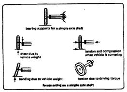
Axle shafts:
The axle shaft
(half shaft) transmits the drive from the differential sun wheel to the rear
hub.
The various
types may be compared by considering the stresses the shaft has to resist. The
half shaft subjects to the following stresses:
|
1- Torsional
stress due to driving and braking torque.
2- Shear
stress due to the weight of the vehicle.
3- Bending
stress due to the vehicle.
4- Tensile and
compressive stress due to cornering forces.
|
|
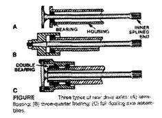
The types of
axle shaft:
In addition to their other features of general construction, driving rear axles
are classified into three groups depending on the type of bearing mounting used
to support the hubs. The three arrangements classified as follows:
|
•
Semi-floating
•
Three-quarter floating
• Fully
floating
|
|
Semi-floating
rear hub:
A single bearing
at the hub end is fitted between the shaft and the casing, so the shaft will
have to resist all the stresses (shear, bending, torsional). In this
arrangement, if the axle shaft breaks, the driving wheel comes away from or out
of the axle housing.
Three-quarter-floating rear hub:
In
this construction the single bearing is located between the hub and the outside
of the axle casing. This relieves the shaft of shear load and bending loads due
to the vehicle’s weight, but it is still subject to bending loads due to
cornering side thrust, and torque. If the shaft fails, the wheel will still be
supported but side loads may cause it to rock on the bearing.
Fully
floating rear hub:
In this
construction the axle is supported by double taper-roller bearings on the
outside of the axle casing. In the frilly floating construction the axle shaft
transmits driving torque alone. The axle removal or failure does not affect the
road wheel, and the disabled vehicle can be towed to a service area to for
replacement of the axle shaft. This system is generally used with heavy
vehicles.
Tires
Types of
tires:
The basic
variations in motor vehicle tire construction may be considered under the
following headings:
• Tube and
tubeless
A separate
rubber inner tube acting as a flexible bag to retain air introduced under
pressure early became an established feature of pneumatic tire Since mid
nineteen fifties it has become established practice for private cars, and to a
lesser extent for commercial vehicle, to dispense with the separate inner tube
in favor of an inherently air-tight or ‘tubeless tire’). The tubeless tire has
the following advantages: (increased safety, cooler running, and Improved
balance).
• Cross ply and
radial play
The radial ply
tire is relatively free from internal friction because of the non-criss-crossing
of its carcass plies. This in turn means cooler running and it permits reduced
inflation pressure for greater cushioning ability.
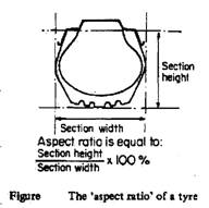
Tire aspect
ratio:
|
It is the
ratio of the tire inflated section height to section width for a specified
rim width. A modern radial ply tire with a ‘low’ aspect ratio is both wider
and shallower than an old fashioned cross ply tire with a ‘high’ aspect
ratio.
The ratio is
usually expressed as a percentage.
|
|