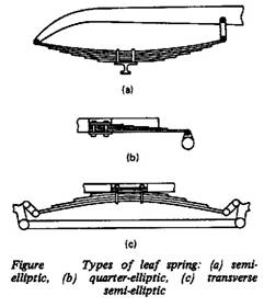
Leaf Springs and Torsion Bars
Leaf Springs
Acts as:
- an elastic element
- guide
- damper
+ they are easy to manufacturer and convincement
to repair
Disadvantage:
-
large
metal
content (energy stored in unit volume in spring or torsion bar is 4 times
more
than a leaf spring; that lead to increase metal content).
-
sufficient
unsprung mass
-
short
service
life.
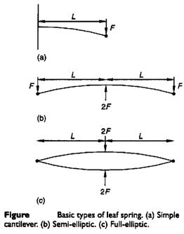
If it is desired to
maintain
uniform bending stresses over the length of the beam then the width of
the
cantilever needs to vary linearly with the location as illustrated in Figure
i,
(σb = M y/I = 12 F L y / b h3). The concept used
in
producing compact cantilever springs of uniform bending stress is to chop
the
triangular form illustrated in Figure i, into a number of strips and
recombine
them as illustrated in Figure ii. The multi-leaf spring shown and the
single
triangular section beam both have the same stress and
deflection
characteristics with the exceptions that the multi-leaf spring is subject
to
additional damping due to friction between the leaves and that the
multi-leaf
spring can carry a full load in only one direction due to the tendency for
the
leaves to separate. Leaf separation can be partially overcome by the
provision
of clips around the leaves.
The deflection of
a
triangular leaf spring is given by

Where
F is force (N)
L is the length (m)
E is the
Young’s
modulus (N/m2)
I is the
second
moment of area (m4)
For a
rectangular
cross-section,

Where b is width (m); and
h
is thickness (m).
The spring rate is given by
The corresponding
bending
stress (for cantilever, semi-elliptic and full-elliptic) is given by
For semi-elliptic beam
the
maximum deflection at the center is given by
For a full-elliptic beam
the
maximum deflection at the center is given by
* in the above equation
the
length b can be changed by (n b’) where n is the number of leafs
and
b’ is the width of single leaf. The leaf width b’
is
chosen from the available range of rolled products. It is desired that
the
following condition should hold
6 < b’/h
< 10
6 < n <
14
The spring length can
be
determined using the equations for spring stiffness and stress to obtain
Where
δ = is the
total deflection (δst + δd)
- Effect of adding an
extra
full length number of leaves (ne) to the graduate length number
of
leaves (ng):
That means the extra
leaves
will have more stress than graduate ones.

Torsion beam suspension (torsion bars)
Definition: A steel bar that is twisted to
support
the weight of the vehicle. Torsion bars are used in place of coil or
leaf
springs on some vehicles, and allow ride height to be adjusted to
compensate
for sage that occurs over time.
The bars are usually solid
of
circular cross section although hollow tubes and rectangular bars are used.
τall = 1000- 1050
MPa
The angle of twist and
stiffness
of a torsion bar are expressed as
The torsion-bar working length
L
(without spline ends) is determined by the θ equation. It is recommended
to choose the diameters and lengths of spline ends depending on the
torsion-bar
diameter
dsp =
(1.2
-1.3)d; and Lsp= (0.6-1.2)d
Suspension Formulae

Where b is the
width
of spring blade (m), L is the distance between the eyes of the
spring
when laden (m), t is the thickness of the blade (m), n is
the
number of blades, and E is the modulus of elasticity, which (modified
to
allow for internal friction) is 159 x 106 kN/m2.
For a torsion bar,
the
spring rate is given as the twisting moment per angular deflection. When
a
lever is added, this can be converted into a rate for the vertical
deflection
of the end of the lever.
Spring rate (torsion
bar,
for deflection at end of lever)
Where G is the
modulus
of rigidity, which is 78.5 x 10⁶ kN/m2 in this case, d
is the diameter of the torsion bar (m), l is the effective length of
the
torsion bar (m), i.e. half the length of the bar for an anti-roll bar, and e
is the length of the lever (m).
Spring rate (coil spring)
Where G is the
modulus
of rigidity, which is 81.5 x 10⁶ kN/m2 in this case, d
is the wire diameter (m), n is the number of free coils, and D
is
the mean coil diameter (m). To find the number of free coils it is necessary
to
subtract the number of dead coils form the total number of coils. The
dead
coils are those that provide the abutment and so cannot be deflected,
usually
1.5 to 2 coils.